743844-015.pdf - 第184页
Processor Internal Pull-Up / Pull- Down on Package Signal Name Pull Up/Pull Down Rail Value (Ω) BPM#[3:0] Pull Up/Pull Down VCC_CFG_PU_OUT 1kOhm PROC_PREQ# Pull Up VCC1p05_PROC 1kOhm PROC_TDI Pull Up VCC1p05_PROC 1kOhm P…
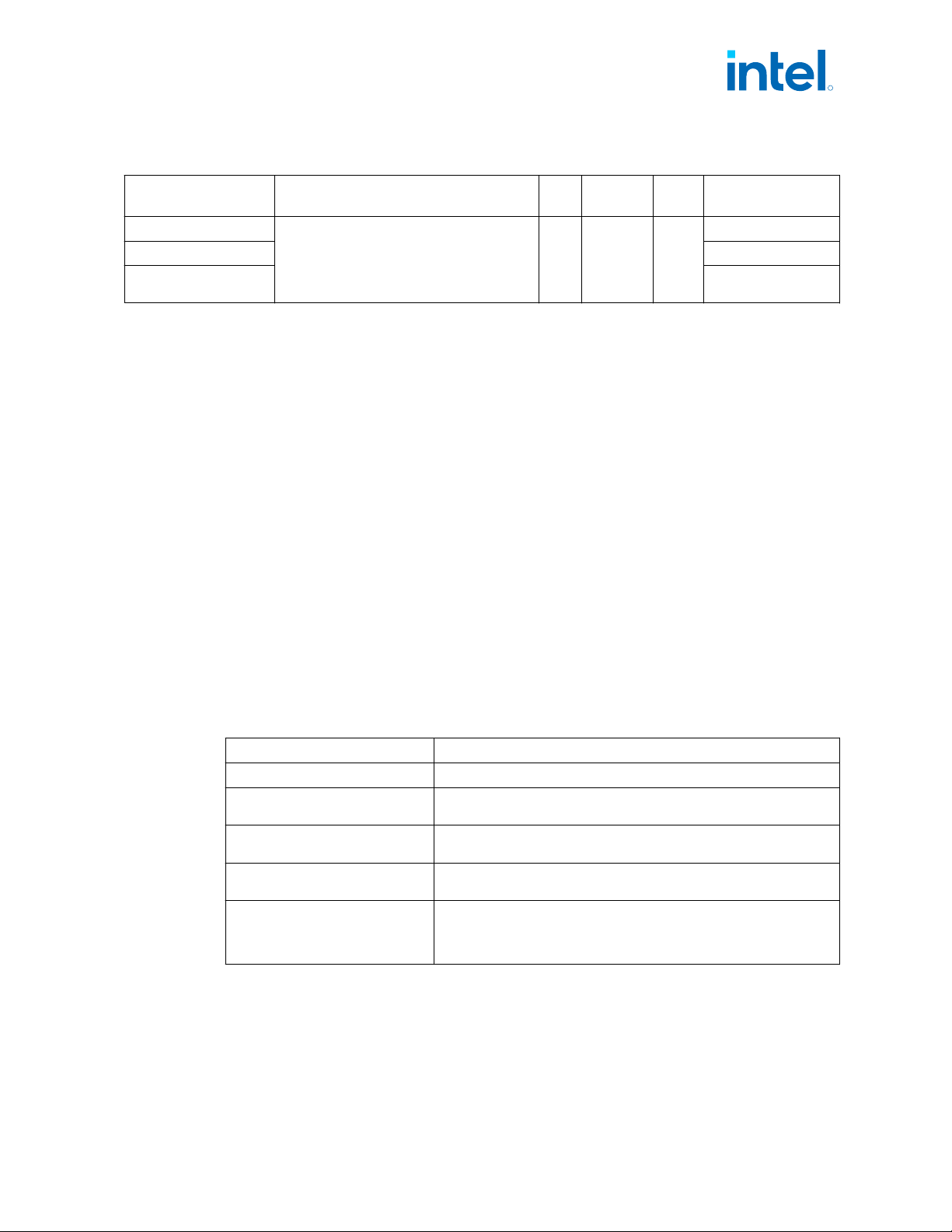
Table 75. Processor Ground Rails Signals
Signal Name Description Dir.
Buffer
Type
Link
Type
Availability
VSSGT_SENSE
Isolated, low impedance Ground sense pins.
They can be used for the reference ground
near the silicon.
N/A
GND_
SENSE
—
All Processor Lines
VSS_SENSE All Processor Lines
VSSIN_AUX_SENSE /
VSSINAUX_SENSE
All Processor Lines
Ground and Reserved Signals
The following are the general types of reserved (RSVD) signals and connection
guidelines:
• RSVD – these signals should not be connected
• RSVD_TP – these signals should be routed to a test point
• _NCTF – these signals are non-critical to function and should not be connected.
Arbitrary connection of these signals to VCC, VDD2, VSS, or to any other signal
(including each other) may result in component malfunction or incompatibility with
future processors. Refer to the table below.
For reliable operation, always connect unused inputs or bi-directional signals to an
appropriate signal level. Unused active high inputs should be connected through a
resistor to ground (VSS). Unused outputs may be left unconnected however, this may
interfere with some Test Access Port (TAP) functions, complicate debug probing and
prevent boundary scan testing. A resistor should be used when tying bi-directional
signals to power or ground. When tying any signal to power or ground the resistor can
also be used for system testability. Resistor values should be within ±20% of the
impedance of the baseboard trace, unless otherwise noted in the appropriate platform
design guidelines.
Table 76. GND, RSVD, and NCTF Signals
Signal Name Description
VSS Ground: Processor ground node
VSS_NCTF
Non-Critical To Function: These signals are for package mechanical
reliability and should not be connected on the board.
RSVD
Reserved: All signals that are RSVD should not be connected on the
board.
RSVD_NCTF
Reserved Non-Critical To Function: RSVD_NCTF should not be
connected on the board.
RSVD_TP
Test Point: Intel recommends to route each RSVD_TP to an accessible
test point. Intel may require these test points for platform specific
debug. Leaving these test points inaccessible could delay debug by
Intel.
12.12
R
Signal Description—Intel
®
Core
™
, Xeon
™
6300 And Xeon
™
E 2400 Processors
13
th
Generation Intel
®
Core
™
, Intel
®
Core
™
14
th
Generation, Intel
®
Core
™
Processor (Series 1) and (Series 2), Intel
®
Xeon
™
E
2400 Processor and Intel
®
Xeon
™
6300 Processor
May 2025 Datasheet, Volume 1 of 2
Doc. No.: 743844, Rev.: 015 183
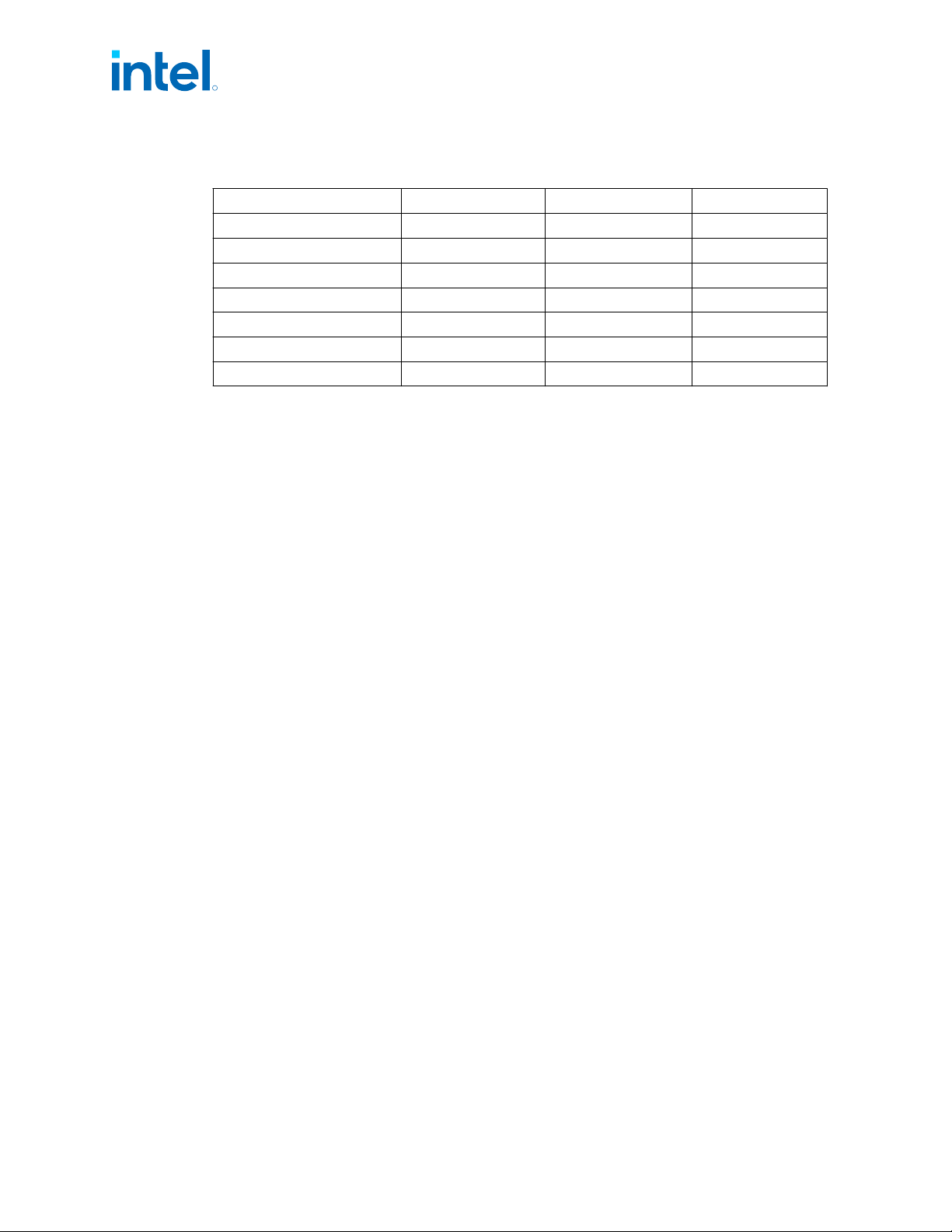
Processor Internal Pull-Up / Pull- Down on Package
Signal Name Pull Up/Pull Down Rail Value (Ω)
BPM#[3:0] Pull Up/Pull Down VCC_CFG_PU_OUT 1kOhm
PROC_PREQ# Pull Up VCC1p05_PROC 1kOhm
PROC_TDI Pull Up VCC1p05_PROC 1kOhm
PROC_TMS Pull Up VCC1p05_PROC 1kOhm
PROC_JTAG_TRST# Pull Down VCC1p05_PROC 1kOhm
PROC_TCK Pull Down VCC1p05_PROC 1kOhm
CFG[17:0] Pull Up VCC_CFG_PU_OUT 1kOhm
12.13
R
Intel
®
Core
™
, Xeon
™
6300 And Xeon
™
E 2400 Processors—Signal Description
13
th
Generation Intel
®
Core
™
, Intel
®
Core
™
14
th
Generation, Intel
®
Core
™
Processor (Series 1) and (Series 2), Intel
®
Xeon
™
E
2400 Processor and Intel
®
Xeon
™
6300 Processor
Datasheet, Volume 1 of 2 May 2025
184 Doc. No.: 743844, Rev.: 015
13.0 Electrical Specifications
Power Delivery
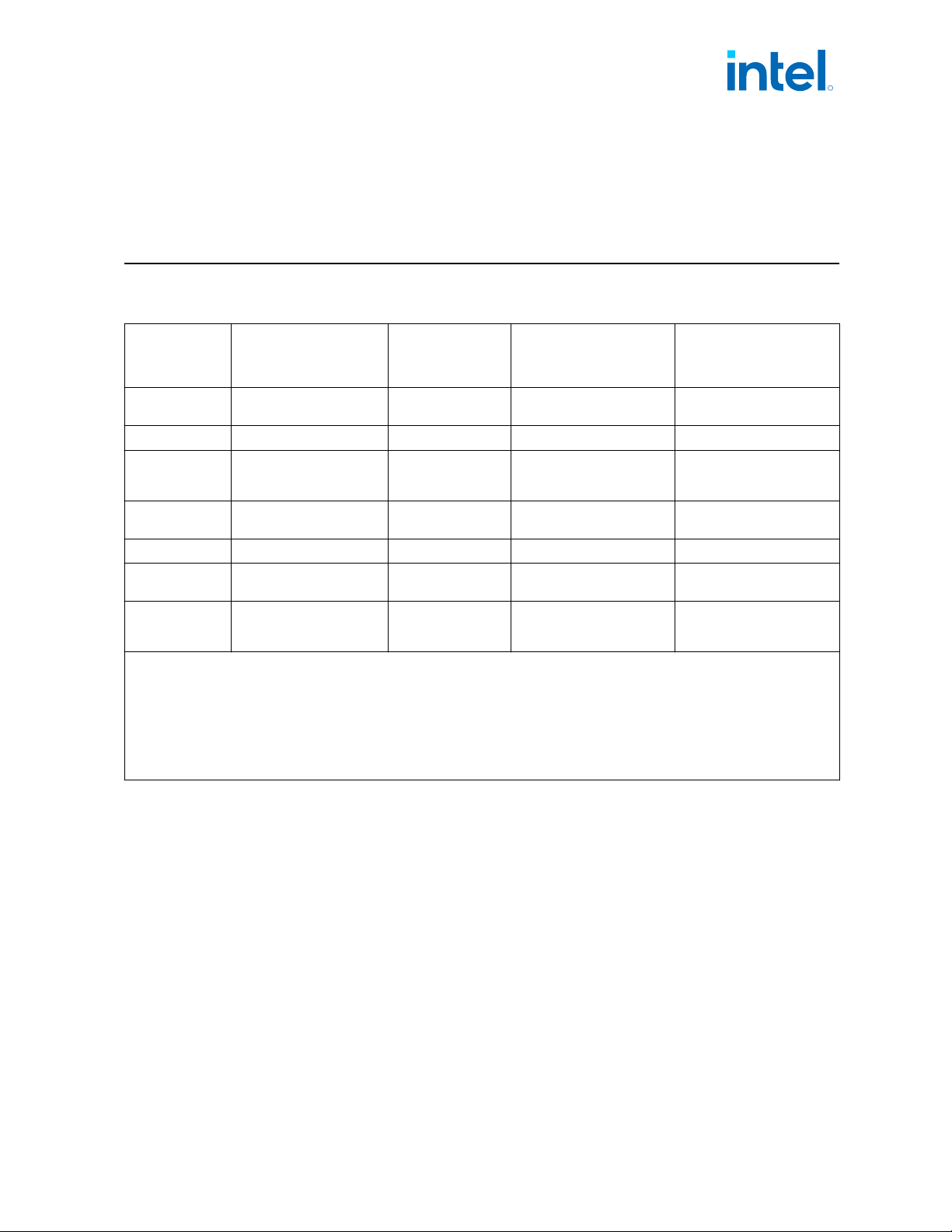
Power Rail Description
S/S Refresh/E/E
Refresh -
Processor Line
Controls
HX/HX Refresh-
Processor Line Controls
P/PX/H/H Refresh/U/U
Refresh Processor Lines
Controls
Vcc
CORE
Processor IA Cores Power
Rail
SVID SVID SVID
Vcc
GT
Graphic Power Rail SVID SVID SVID
Vcc
IN_AUX
3
Support internal FIVR’s 1,
SA, PCIe, Display IO and
other internal Blocks.
PCH VID PCH VID PCH VID
Vcc
1P05_PROC
4
Sustain and Sustain
Gated Power Rail
Fixed Fixed Fixed
Vcc
1p8_PROC
PCIE PHY Power 1.8V Rail Fixed Fixed Fixed
Vcc
MIPILP
DDI PHY power rail for
MIPI DSI interface
------ ------ Fixed
V
DD2
Integrated Memory
Controller Power Rail
Fixed (Memory
technology
dependent)
Fixed (Memory technology
dependent)
Fixed (Memory technology
dependent)
Notes: 1. FIVR = Fully Integrated Voltage Regulator. For details, refer to Digital Linear Voltage Regulator (DLVR) on page
185.
2. Vcc
IN_AUX
has a few discrete voltages defined by PCH VID.
3. VCC
1P05_PROC
, for S processor the power rail is connected to a platform voltage regulator to supply power to the
sustaining power rails.
4. Vcc
MIPILP
: When MIPI DSI interface is been used, this power rail should be connected to 1.24V rail.
5. VCC
1P05_PROC
for P-Processor line power rail is connected to VCC1P05_OUT_FET rail through a power gate at
platform, to supply power to the sustain gated power rails.
Power and Ground Pins
All power pins should be connected to their respective processor power planes, while
all VSS pins should be connected to the system ground plane. Use of multiple power
and ground planes is recommended to reduce I*R drop.
Digital Linear Voltage Regulator (DLVR)
The processor has few internal DLVRs to power gate VccCore, VccGT, and VccSA power
rails.
DLVR is internal VR consumes lower power and works within a lower temperature
range.
13.1
13.1.1
13.1.2
R
Electrical Specifications—Intel
®
Core
™
, Xeon
™
6300 And Xeon
™
E 2400 Processors
13
th
Generation Intel
®
Core
™
, Intel
®
Core
™
14
th
Generation, Intel
®
Core
™
Processor (Series 1) and (Series 2), Intel
®
Xeon
™
E
2400 Processor and Intel
®
Xeon
™
6300 Processor
May 2025 Datasheet, Volume 1 of 2
Doc. No.: 743844, Rev.: 015 185