743844-015.pdf - 第45页
instruction in the program stream must be an ENDBRANCH. If an ENDBRANCH is not seen the processor causes a control protection fault (#CP), otherwise the state machine moves back to IDLE state. More information on Intel ®…

Data in-memory and on the external memory buses is encrypted and exists in plain
text only inside the processor. This allows existing software to operate without any
modification while protecting memory using Intel TME. Intel TME does not protect
memory from modifications.
Intel TME allows the BIOS to specify a physical address range to remain unencrypted.
Software running on Intel TME enabled system has full visibility into all portions of
memory that are configured to be unencrypted by reading a configuration register in
the processor.
NOTES
• Memory access to nonvolatile memory (Intel
®
Optane
™
) is encrypted as well.
• More information on Intel TME-MK can be found at:
https://software.intel.com/sites/default/files/managed/a5/16/Total-Memory-
Encryption-Multi-Key-Spec.pdf
• A cold boot is required when enable/ disable Intel TME feature on this platform.
Intel
®
Control-flow Enforcement Technology
Return-oriented Programming (ROP), and similarly CALL/JMP-oriented programming
(COP/JOP), have been the prevalent attack methodology for stealth exploit writers
targeting vulnerabilities in programs.
Intel
®
Control-flow Enforcement Technology (Intel
®
CET) provides the following
components to defend against ROP/JOP style control-flow subversion attacks:
Shadow Stack
A shadow stack is a second stack for the program that is used exclusively for control
transfer operations. This stack is separate from the data stack and can be enabled for
operation individually in user mode or supervisor mode.
The shadow stack is protected from tamper through the page table protections such
that regular store instructions cannot modify the contents of the shadow stack. To
provide this protection the page table protections are extended to support an
additional attribute for pages to mark them as “Shadow Stack” pages. When shadow
stacks are enabled, control transfer instructions/flows such as near call, far call, call to
interrupt/exception handlers, etc. store their return addresses to the shadow stack.
The RET instruction pops the return address from both stacks and compares them. If
the return addresses from the two stacks do not match, the processor signals a
control protection exception (#CP). Stores from instructions such as MOV, XSAVE, etc.
are not allowed to the shadow stack.
Indirect Branch Tracking
The ENDBR32 and ENDBR64 (collectively ENDBRANCH) are two new instructions that
are used to mark valid indirect CALL/JMP target locations in the program. This
instruction is a NOP on legacy processors for backward compatibility.
The processor implements a state machine that tracks indirect JMP and CALL
instructions. When one of these instructions is seen, the state machine moves from
IDLE to WAIT_FOR_ENDBRANCH state. In WAIT_FOR_ENDBRANCH state the next
2.3.13
2.3.13.1
2.3.13.2
R
Intel
®
Core
™
, Xeon
™
6300 And Xeon
™
E 2400 Processors—Technologies
13
th
Generation Intel
®
Core
™
, Intel
®
Core
™
14
th
Generation, Intel
®
Core
™
Processor (Series 1) and (Series 2), Intel
®
Xeon
™
E
2400 Processor and Intel
®
Xeon
™
6300 Processor
Datasheet, Volume 1 of 2 May 2025
44 Doc. No.: 743844, Rev.: 015

instruction in the program stream must be an ENDBRANCH. If an ENDBRANCH is not
seen the processor causes a control protection fault (#CP), otherwise the state
machine moves back to IDLE state.
More information on Intel
®
CET can be found at:
https://software.intel.com/sites/default/files/managed/4d/2a/control-flow-
enforcement-technology-preview.pdf
KeyLocker Technology
A method to make long-term keys short-lived without exposing them. This protects
against vulnerabilities when keys can be exploited and used to attack encrypted data
such as disk drives.
An instruction (LOADIWKEY) allows the OS to load a random wrapping value (IWKey).
The IWKey can be backed up and restored by the OS to/from the PCH in a secure
manner.
The Software can wrap it own key via the ENCODEKEY instruction and receive a
handle. The handle is used with the AES*KL instructions to handle encrypt and
decrypt operations. Once a handle is obtained, the software can delete the original key
from memory.
Devil’s Gate Rock
Devil’s Gate Rock (DGR) is a BIOS hardening technology that splits SMI (System
Management Interrupts) handlers into Ring 3 and Ring 0 portions.
Supervisor/user paging on the smaller Ring 0 portion will enforce access policy for all
the ring 3 code with regard to the SMM state save, MSR registers, IO ports and other
registers.
The Ring 0 portion can perform save/restore of register context to allow the Ring 3
section to make use of those registers without having access to the OS context or the
ability to modify the OS context.
The Ring 0 portion is signed and provided by Intel. This portion is attested by the
processor.
Power and Performance Technologies
Intel
®
Smart Cache Technology
The Intel
®
Smart Cache Technology is a shared Last Level Cache (LLC).
• The LLC is non-inclusive.
• The LLC may also be referred to as a 3rd level cache.
• The LLC is shared between all IA cores as well as the Processor Graphics.
• For P Cores The 1st and 2nd level caches are not shared between physical cores
and each physical core has a separate set of caches.
• For E Cores The 1st level cache is not shared between physical cores and each
physical core has a separate set of caches.
2.3.14
2.3.15
2.4
2.4.1
R
Technologies—Intel
®
Core
™
, Xeon
™
6300 And Xeon
™
E 2400 Processors
13
th
Generation Intel
®
Core
™
, Intel
®
Core
™
14
th
Generation, Intel
®
Core
™
Processor (Series 1) and (Series 2), Intel
®
Xeon
™
E
2400 Processor and Intel
®
Xeon
™
6300 Processor
May 2025 Datasheet, Volume 1 of 2
Doc. No.: 743844, Rev.: 015 45
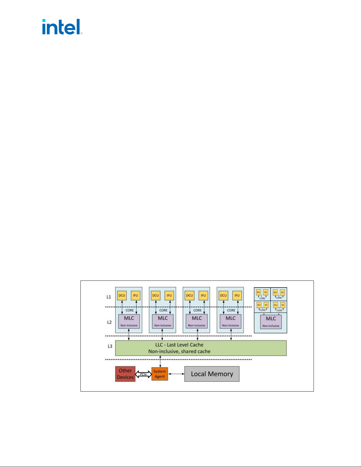
• For E Cores The 2nd level cache is shared between 4 physical cores.
• The size of the LLC is SKU specific with a maximum of 3MB per P physical core or
4 E cores and is a 12-way associative cache.
IA Cores Level 1 and Level 2 Caches
P Cores 1st level cache is divided into a data cache (DFU) and an instruction cache
(IFU). The processor 1st level cache size is 48KB for data and 32KB for instructions.
The 1st level cache is an 12-way associative cache.
E Cores 1st level cache is divided into a data cache (DFU) and an instruction cache
(IFU). The processor 1st level cache size is 32KB for data and 64KB for instructions.
The 1st level cache is an 8-way associative cache.
The 2nd level cache holds both data and instructions. It is also referred to as mid-level
cache or MLC.
For P/H/H Refresh/U, S/HX 8P+8E, S 6P+0E predecessor lines, the P Cores 2nd level
cache size is 1.25 MB and is a 10-way non-inclusive associative cache, 4 E Cores
processors 2nd level cache size is 2MB and is a 16-way non-inclusive associative
cache.
For S refresh 8P+8E, S refresh 6P+0E predecessor lines, the P Cores 2nd level cache
size is 1.25 MB and is a 10-way non-inclusive associative cache, 4 E Cores processors
2nd level cache size is 2MB and is a 16-way non-inclusive associative cache.
For S/HX 8P+16E and E Processors Lines, the P Cores 2nd level cache size is2 MB and
is a 16-way non-inclusive associative cache, 4 E Cores processors 2nd level cache size
is 4MB and is a 16-way non-inclusive associative cache.
For S Refresh/HX Refresh 8P+16E Processors Lines, the P Cores 2nd level cache size is
2 MB and is a 16-way non-inclusive associative cache, 4 E Cores processors 2nd level
cache size is 4MB and is a 16-way non-inclusive associative cache
Figure 11. Hybrid Cache
2.4.2
R
Intel
®
Core
™
, Xeon
™
6300 And Xeon
™
E 2400 Processors—Technologies
13
th
Generation Intel
®
Core
™
, Intel
®
Core
™
14
th
Generation, Intel
®
Core
™
Processor (Series 1) and (Series 2), Intel
®
Xeon
™
E
2400 Processor and Intel
®
Xeon
™
6300 Processor
Datasheet, Volume 1 of 2 May 2025
46 Doc. No.: 743844, Rev.: 015