743844-015.pdf - 第63页
Figure 14. Processor Package and IA Core C-States 1. PkgC2/C3 are non-architectural: softw are cannot request to enter these states explicitly . These states are intermediate states between PkgC0 and PkgC6. 2. There are …
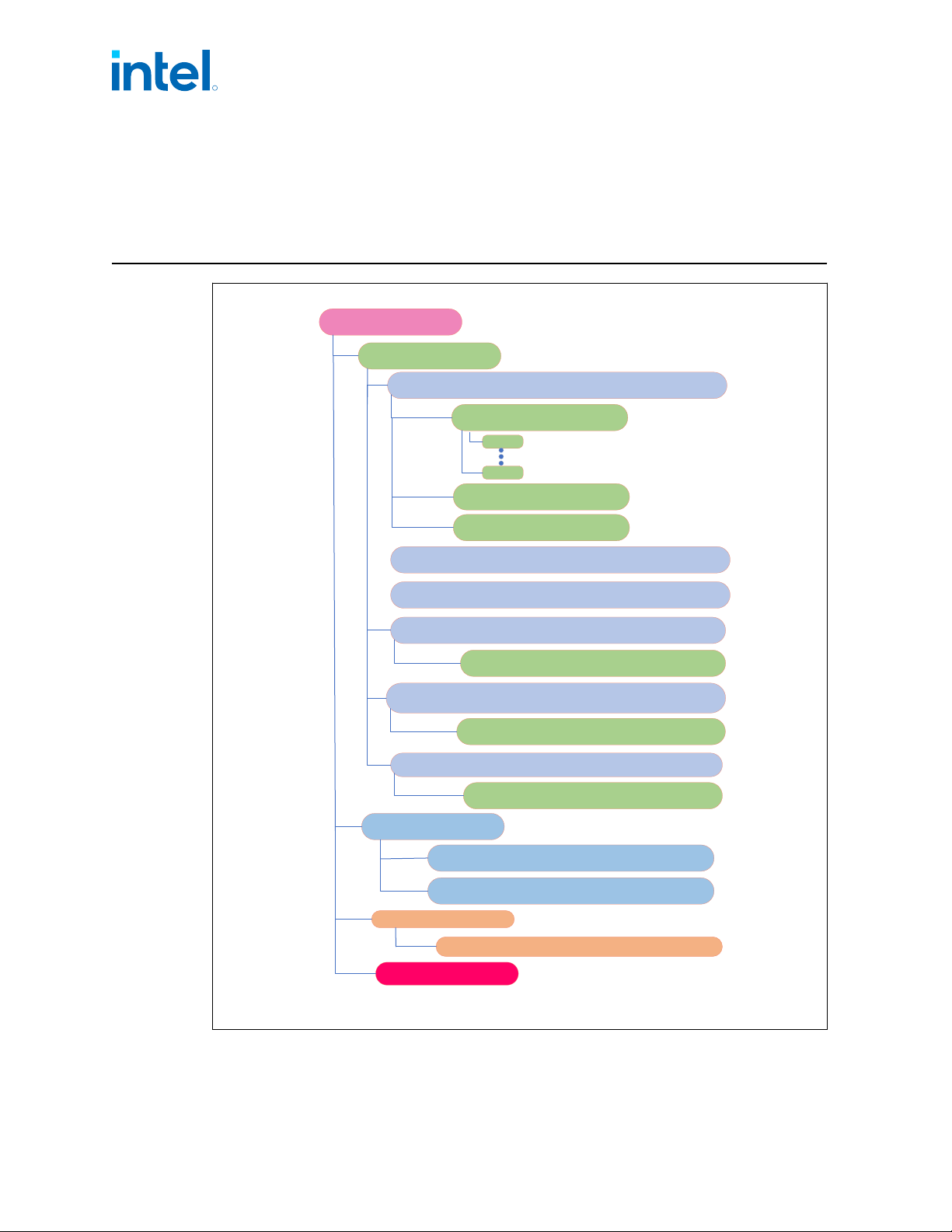
3.0 Power Management
Package C6
Package C3 + LLC is not flushed, uncore clocks stopped
Package C0
G0- Working
S0- Processor Powered On
P0
C0- Active Mode
Pn
C1- Auto Halt
C1E- Auto Halt, can be in low frequency and low
voltage
C6- All core clocks are stopped, core state saved, voltage reduced to 0v
Package C8
Package C6 + LLC is flushed at once, Display engine stays on
C8- LLC is flushed at once, Display engine still stays on.
Package C10
Package C8 + All VR’s at PS4 or LPM
C10 All VRs at PS4 or LPM + Display PSR/OFF
Package C3
Package C2 and Memory refresh
Package C2
Package C0 and Memory is active
G2- Soft off
S5- Power off , Wakeup on PCH
G3- Mechanical off
G1- Sleeping
S4- Hibernate- Suspend to Disk (STD), Wakeup on PCH
Wakeup on processor
S3- Hibernate- Suspend to RAM (STR), Wakeup on PCH
Wakeup on processor
R
Intel
®
Core
™
, Xeon
™
6300 And Xeon
™
E 2400 Processors—Power Management
13
th
Generation Intel
®
Core
™
, Intel
®
Core
™
14
th
Generation, Intel
®
Core
™
Processor (Series 1) and (Series 2), Intel
®
Xeon
™
E
2400 Processor and Intel
®
Xeon
™
6300 Processor
Datasheet, Volume 1 of 2 May 2025
62 Doc. No.: 743844, Rev.: 015
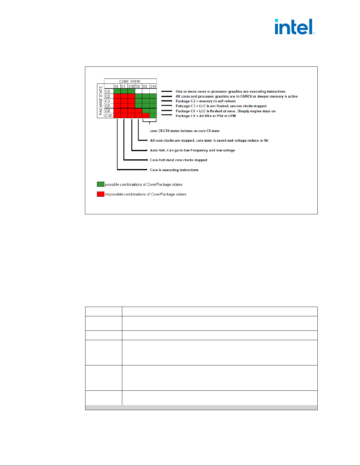
Figure 14. Processor Package and IA Core C-States
1. PkgC2/C3 are non-architectural: software cannot request to enter these states
explicitly. These states are intermediate states between PkgC0 and PkgC6.
2. There are constraints that prevent the system to go deeper.
3. The “core state” relates to the core which is in the HIGEST power state in the
package (most active).
Advanced Configuration and Power Interface (ACPI)
States Supported
This section describes the ACPI states supported by the processor.
Table 4. System States
State Description
G0/S0/C0
Full On: CPU operating. Individual devices may be shut to save power. The different CPU
operating levels are defined by Cx states.
GO/S0/Cx Cx state: CPU manages C-states by itself and can be in low power state
G1/S3
Suspend-To-RAM (STR): The system context is maintained in system DRAM, but power
is shut to non-critical circuits. Memory is retained, and refreshes continue. All external
clocks are shut off; RTC clock and internal ring oscillator clocks are still toggling.
In S3, SLP_S3 signal stays asserted, SLP_S4 and SLP_S5 are inactive until a wake occurs.
G1/S4
Suspend-To-Disk (STD): The context of the system is maintained on the disk. All power
is then shut to the system except to the logic required to resume. Externally appears same
as S5 but may have different wake events.
In S4, SLP_S3 and SLP_S4 both stay asserted and SLP_S5 is inactive until a wake occurs.
G2/S5
Soft Off: System context not maintained. All power is shut except for the logic required to
restart. A full boot is required when waking.
continued...
3.1
R
Power Management—Intel
®
Core
™
, Xeon
™
6300 And Xeon
™
E 2400 Processors
13
th
Generation Intel
®
Core
™
, Intel
®
Core
™
14
th
Generation, Intel
®
Core
™
Processor (Series 1) and (Series 2), Intel
®
Xeon
™
E
2400 Processor and Intel
®
Xeon
™
6300 Processor
May 2025 Datasheet, Volume 1 of 2
Doc. No.: 743844, Rev.: 015 63
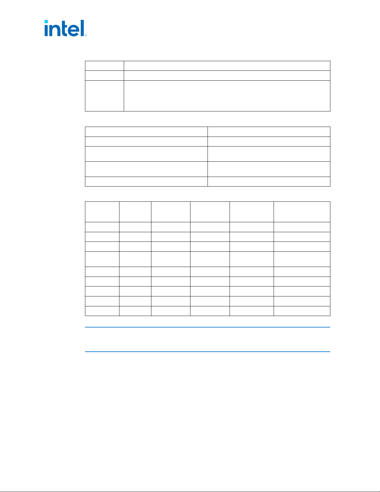
State Description
Here, SLP_S3, SLP_S4, and SLP_S5 are all active until a wake occurs.
G3
Mechanical OFF: System context not maintained. All power shut except for the RTC. No
“Wake” events are possible because the system does not have any power. This state occurs
if the user removes the batteries, turns off a mechanical switch, or if the system power
supply is at a level that is insufficient to power the “waking” logic. When system power
returns the transition will depend on the state just prior to the entry to G3.
Table 5. Integrated Memory Controller (IMC) States
State Description
Power-Up CKE asserted. Active mode.
Pre-Charge Power Down CKE de-asserted (not self-refresh) with all banks
closed.
Active Power Down CKE de-asserted (not self-refresh) with minimum
one bank active.
Self-Refresh CKE de-asserted using device self-refresh.
Table 6. G, S, and C Interface State Combinations
Global (G)
State
Sleep (S)
State
Processor
Package (C)
State
Processor
State
System Clocks Description
G0 S0 C0 Full On On Full On
G0 S0 C2
1
Deep Sleep On Deep Sleep
G0 S0 C3
1
Deep Sleep On Deep Sleep
G0 S0 C6
Deep Power
Down
On Deep Power Down
G0 S0 C8/C10 Off On Deeper Power Down
G1 S3 Power off Off Off, except RTC Suspend to RAM
G1 S4 Power off Off Off, except RTC Suspend to Disk
G2 S5 Power off Off Off, except RTC Soft Off
G3 N/A Power off Off Power off Hard off
NOTE
1. PkgC2/C3 are non-architectural: software cannot request to enter these states
explicitly. These states are intermediate states between PkgC0 and PkgC6.
Processor IA Core Power Management
While executing code, Enhanced Intel SpeedStep
®
Technology and Intel
®
Speed Shift
technology optimizes the processor’s IA core frequency and voltage based on
workload. Each frequency and voltage operating point is defined by ACPI as a P-state.
When the processor is not executing code, it is idle. A low-power idle state is defined
by ACPI as a C-state. In general, deeper power C-states have longer entry and exit
latencies.
3.2
R
Intel
®
Core
™
, Xeon
™
6300 And Xeon
™
E 2400 Processors—Power Management
13
th
Generation Intel
®
Core
™
, Intel
®
Core
™
14
th
Generation, Intel
®
Core
™
Processor (Series 1) and (Series 2), Intel
®
Xeon
™
E
2400 Processor and Intel
®
Xeon
™
6300 Processor
Datasheet, Volume 1 of 2 May 2025
64 Doc. No.: 743844, Rev.: 015