743844-015.pdf - 第74页
PCI Express* Power Management • Active power management support using L0s (see below), L1 Substates(L1.1,L1.2) • L0s is supported across all PEG interfaces. • All inputs and outputs disabled in L2/L3 Ready state. • S Pro…

controller. The graphics driver dynamically adjusts between P-States to maintain
optimal performance, power, and thermals. The graphics driver will always place the
graphics engine in its lowest possible P-State. Intel
®
Graphics Dynamic Frequency
requires BIOS support. Additional power and thermal budget should be available.
Intel
®
Graphics Render Standby Technology (Intel
®
GRST)
Intel
®
Graphics Render Standby Technology is a technique designed to optimize the
average power of the graphics part. The Graphics Render engine will be put in a sleep
state, or Render Standby (RS), during times of inactivity or basic video modes. While
in Render Standby state, the graphics part will place the VR (Voltage Regulator) into a
low voltage state. Hardware will save the render context to the allocated context
buffer when entering RS state and restore the render context upon exiting RS state.
Intel Capped Frames Per Second (CFPS)
Intel Capped Frames Per Second is a feature developed to save power during High FPS
Gaming workloads while also achieving a tear and stutter free visual experience.
This feature ensures that the frame rate of the game does not exceed the panel
refresh rate by matching screen updates to the Vertical Sync. That results fewer
wakeups of graphics core and saves power.
When enabled, this feature works on any display panel, AC or DC mode and on any
gaming workload.
System Agent Enhanced Intel SpeedStep
®
Technology
System Agent Enhanced Intel SpeedStep
®
Technology is a dynamic voltage frequency
scaling of the System Agent clock based on memory utilization. Unlike processor core
and package Enhanced Intel SpeedStep
®
Technology, System Agent Enhanced Intel
SpeedStep
®
Technology has three valid operating points. When running light workload
and SA Enhanced Intel SpeedStep
®
Technology is enabled, the DDR data rate may
change as follows:
BIOS/MRC DDR training at maximum, mid and minimum frequencies sets I/O and
timing parameters.
In order to achieve the optimal levels of performance and power, the memory
initialization and training process performed during first system boot or after
CMOS clear or after a BIOS update will take a longer time than a typical boot.
During this initialization and training process, end users may see a blank
screen. More information on the memory initialization process can be found
in the industry standard JEDEC Specifications found on www.JEDEC.org.
Before changing the DDR data rate, the processor sets DDR to self-refresh and
changes the needed parameters. The DDR voltage remains stable and unchanged.
Rest Of Platform (ROP) PMIC
In addition to discrete voltage regulators, Intel supports specific PMIC (Power
Management Integrated Circuit) models to power the ROP rails. PMICs are typically
classified as “Premium” or “Volume” ROP PMICs.
3.5
3.6
R
Power Management—Intel
®
Core
™
, Xeon
™
6300 And Xeon
™
E 2400 Processors
13
th
Generation Intel
®
Core
™
, Intel
®
Core
™
14
th
Generation, Intel
®
Core
™
Processor (Series 1) and (Series 2), Intel
®
Xeon
™
E
2400 Processor and Intel
®
Xeon
™
6300 Processor
May 2025 Datasheet, Volume 1 of 2
Doc. No.: 743844, Rev.: 015 73
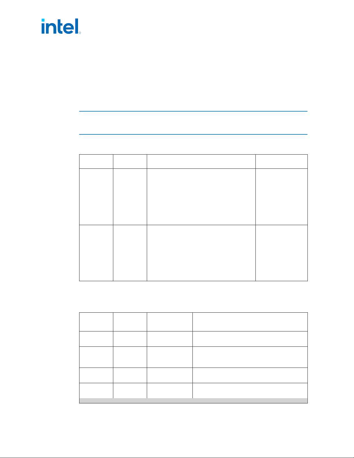
PCI Express* Power Management
• Active power management support using L0s (see below), L1 Substates(L1.1,L1.2)
• L0s is supported across all PEG interfaces.
• All inputs and outputs disabled in L2/L3 Ready state.
• S Processor PCIe* interface does not support Hot-Plug.
NOTE
An increase in power consumption may be observed when PCI Express* ASPM
capabilities are disabled.
Table 9. Package C-States with PCIe* Link States Dependencies
Processor
Interface
L-State Description Package C-State
PCIe*
L1.0 or
deeper
L1- Higher latency, lower power “standby” state
L2 – Auxiliary-powered Link, deep-energy-saving
state.
Disabled - The intent of the Disabled state is to
allow a configured Link to be disabled until
directed or Electrical Idle is exited (that is, due to
a hot removal and insertion) after entering
Disabled.
No Device Attached - no physical device is
attached on PEG port
PC6-PC8
PCIe*
L1.2 or
deeper
L1- Higher latency, lower power “standby” state
L2 – Auxiliary-powered Link, deep-energy-saving
state.
Disabled - The intent of the Disabled state is to
allow a configured Link to be disabled until
directed or Electrical Idle is exited (that is, due to
a hot removal and insertion) after entering
Disabled.
No Device Attached - no physical device is
attached on PEG port
PC10
TCSS Power State
Table 10. TCSS Power State
TCSS Power
State
Allowed
Package C
Status
Device Attached Description
TC0 PC0-PC3
Yes xHCI, xDCI, USB4 controllers may be active.
USB4 DMA / PCIe may be active.
TC7 PC6-PC10
Yes xHCI and xDCI are in D3.
USB4 controller is in D3 or D0 idle.
USB4 PCIe is inactive.
TC-Cold PC3-PC10
No xHCI / xDCI / TBT DMA / TBT PCIe are in D3
IOM is active
TC10 PC6-PC10 No
Deepest Power state
xHCI and xDCI are in D3. USB4 is in D3 or D0 idle.
continued...
3.7
3.8
R
Intel
®
Core
™
, Xeon
™
6300 And Xeon
™
E 2400 Processors—Power Management
13
th
Generation Intel
®
Core
™
, Intel
®
Core
™
14
th
Generation, Intel
®
Core
™
Processor (Series 1) and (Series 2), Intel
®
Xeon
™
E
2400 Processor and Intel
®
Xeon
™
6300 Processor
Datasheet, Volume 1 of 2 May 2025
74 Doc. No.: 743844, Rev.: 015

TCSS Power
State
Allowed
Package C
Status
Device Attached Description
USB4 CIe is in inactive
IOM is inactive
IOM - TCSS Input Output Manager:
• The IOM interacts with the SoC to perform power management, boot, reset, connect and disconnect
devices to TYPE-C sub-system
TCSS Devices (xHCI / xDCI / TBT Controllers) - power states:
• D0 - Device at Active state.
• D3 - Device at lowest-powered state.
R
Power Management—Intel
®
Core
™
, Xeon
™
6300 And Xeon
™
E 2400 Processors
13
th
Generation Intel
®
Core
™
, Intel
®
Core
™
14
th
Generation, Intel
®
Core
™
Processor (Series 1) and (Series 2), Intel
®
Xeon
™
E
2400 Processor and Intel
®
Xeon
™
6300 Processor
May 2025 Datasheet, Volume 1 of 2
Doc. No.: 743844, Rev.: 015 75