743844-015.pdf - 第204页
Symbol Parameter Segment Minimum Typical Maximum Unit Note 1 DC_LL (PX Processors) DC Loadline PX -Processor Line — — 3.2 mΩ 7, 9, 10 DC_LL (U/P/H Processors) DC Loadline U /U Refresh/P/H/H Refresh - Processor Line — — 3…
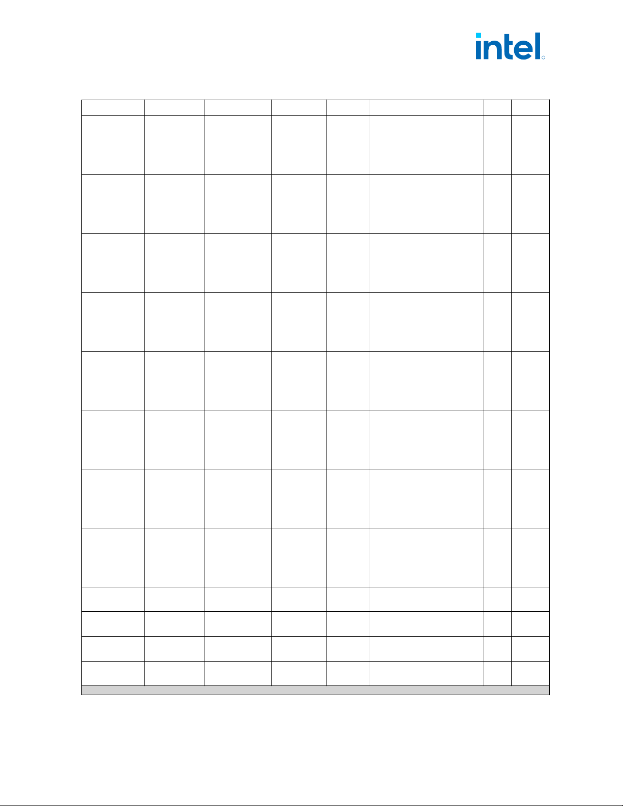
Symbol Parameter Segment Minimum Typical Maximum Unit Note
1
Icc
TDC_GT
Thermal
Design
Current
(TDC) for
Processor
Graphics Rail
S/S Refresh-
Processor Line
(125W)
— — 22 A 6
Icc
TDC_GT
Thermal
Design
Current
(TDC) for
Processor
Graphics Rail
S/S Refresh-
Processor Line
(65W)
— — 22 A 6
Icc
TDC_GT
Thermal
Design
Current
(TDC) for
Processor
Graphics Rail
S/S Refresh-
Processor Line
(35W)
— — 22/20 A 6
Icc
TDC_GT
Thermal
Design
Current
(TDC) for
Processor
Graphics Rail
HX /HX Refresh
Processor Line
(55W)
— — 22 A 6
Icc
TDC_GT
Thermal
Design
Current
(TDC) for
Processor
Graphics Rail
H/H Refresh-
Processor Line
(45W)
— — 35 A 6
Icc
TDC_GT
Thermal
Design
Current
(TDC) for
Processor
Graphics Rail
P-Processor
Line
(28W)
— — 35 A 6
Icc
TDC_GT
Thermal
Design
Current
(TDC) for
Processor
Graphics Rail
PX-Processor
Line
(45W)
— — 35 A 6
Icc
TDC_GT
Thermal
Design
Current
(TDC) for
Processor
Graphics Rail
U /U Refresh-
Processor Line
(15W)
— — 23 A 6
TOB
VCCGT
Voltage
Tolerance
PS0, PS1 ,PS2,
PS3
— — ±20 mV 3,4
TOB
VCCGT
+Ripple
Ripple
Tolerance
PS0, PS1, PS2,
PS3
— — -35 /+50 mV 3, 4,13
DC_LL ( S
Processors)
DC Loadline
S/S Refresh -
Processor Line
— — 4.0 mΩ 7, 9, 10
DC_LL ( HX
Processors)
DC Loadline
HX /HX Refresh
-Processor Line
— — 4.0 mΩ 7, 9, 10
continued...
R
Electrical Specifications—Intel
®
Core
™
, Xeon
™
6300 And Xeon
™
E 2400 Processors
13
th
Generation Intel
®
Core
™
, Intel
®
Core
™
14
th
Generation, Intel
®
Core
™
Processor (Series 1) and (Series 2), Intel
®
Xeon
™
E
2400 Processor and Intel
®
Xeon
™
6300 Processor
May 2025 Datasheet, Volume 1 of 2
Doc. No.: 743844, Rev.: 015 203
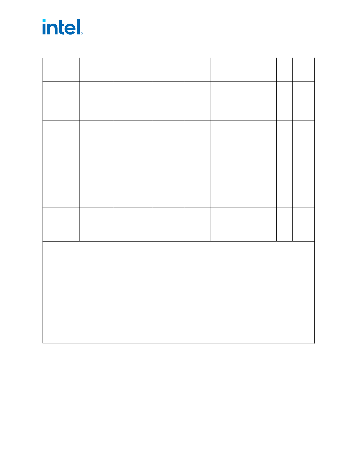
Symbol Parameter Segment Minimum Typical Maximum Unit Note
1
DC_LL (PX
Processors)
DC Loadline
PX-Processor
Line
— — 3.2 mΩ 7, 9, 10
DC_LL (U/P/H
Processors)
DC Loadline
U /U
Refresh/P/H/H
Refresh -
Processor Line
— — 3.2 mΩ 7, 9, 10
AC_LL (S
Processors)
AC Loadline
S/S Refresh -
Processor Line
— — 4.0 mΩ 7, 9, 10
AC_LL (HX
Processors)
AC Loadline
HX /HX Refresh
-Processor Line
— —
• Below 300KHz: 4.0
• 300KHz-1MHz: linear
decrease with
log(frequency) from 4.0
to 3.0
• Above 1MHz: 3.0
mΩ 7, 9, 10
AC_LL (PX
Processors)
AC Loadline
PX-Processor
Line
— — 3.2 mΩ 7, 9, 10
AC_LL (U/P/H
Processors)
AC Loadline
U /U
Refresh/P/H/H
Refresh -
Processor Line
— —
• Below 400kHz: 3.2
• 400kHz-2MHz: linear
decrease with log
(frequency) from 3.2 to
2.4
• Above 2MHz: 2.4
mΩ
7, 9,
10,12
T_OVS_MAX
Max
Overshoot
time
—
— — 10 µs
V_OVS_MAX
Max
Overshoot
—
— — 70 mV
Notes: 1. All specifications in this table are based on estimates and simulations or empirical data. These specifications will
be updated with characterized data from silicon measurements at a later date.
2. Each processor is programmed with a maximum valid voltage identification value (VID), which is set at
manufacturing and cannot be altered. Individual maximum VID values are calibrated during manufacturing such
that two processors at the same frequency may have different settings within the VID range. This differs from
the VID employed by the processor during a power or thermal management event (Intel Adaptive Thermal
Monitor, Enhanced Intel
®
SpeedStep Technology, or low-power states).
3. PSx refers to the voltage regulator power state as set by the SVID protocol.
4. Each processor is programmed with a maximum valid voltage identification value (VID), which is set at
manufacturing and cannot be altered. Individual maximum VID values are calibrated during manufacturing such
that two processors at the same frequency may have different settings within the VID range. This differs from
the VID employed by the processor during a power or thermal management event (Intel Adaptive Thermal
Monitor, Enhanced Intel
®
SpeedStep Technology, or low-power states).
5. Operating voltage range in steady state.
6. Load Line measured at the sense point.
7. An IMVP9.1 controller to support VCCGT need to have an offset voltage capability and potentially VCCGT output
voltage (VID+Offset) may be higher than 1.5V
8. Ripple can be higher if DC TOB is below 20mV, as long as Total TOB is within -35mV/+50mV.
R
Intel
®
Core
™
, Xeon
™
6300 And Xeon
™
E 2400 Processors—Electrical Specifications
13
th
Generation Intel
®
Core
™
, Intel
®
Core
™
14
th
Generation, Intel
®
Core
™
Processor (Series 1) and (Series 2), Intel
®
Xeon
™
E
2400 Processor and Intel
®
Xeon
™
6300 Processor
Datasheet, Volume 1 of 2 May 2025
204 Doc. No.: 743844, Rev.: 015
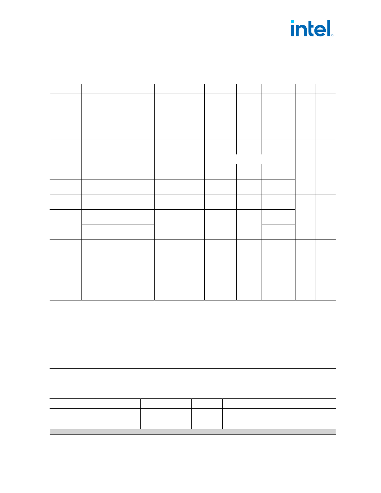
V
DD2
DC Specifications
Table 83. Memory Controller (VDD2) Supply DC Voltage and Current Specifications
Symbol Parameter Segment Minimum Typical Maximum Unit Note
1
V
DD2(LPDDR4x
)
Processor I/O supply voltage
for LPDDR4x
All Processor Lines Typ-5% 1.115 Typ+5% V 3,4,5
V
DD2
(LPDDR5/x)
Processor I/O supply voltage
for LPDDR5/x
All Processor Lines Typ-5% 1.065 Typ+5% V 3,4,5
V
DD2 (DDR4)
Processor I/O supply voltage
for DDR4
All Processor Lines Typ-5% 1.2 Typ+5% V 3,4,5
V
DD2 (DDR5)
Processor I/O supply voltage
for DDR5
All Processor Lines Typ-4.5% 1.116 Typ+4.5% V 3,4,5
TOB
VDD2
VDD2 Tolerance All Processor Lines VDD2 MIN <AC+DC< VDD2 MAX V 3,4
Icc
MAX_VDD2
(LPDDR4x)
Maximum Current for V
DD2
Rail (LPDDR4x)
P/H/PX-Processor
Line
— — 2.6
A 2
Icc
MAX_VDD2
(LPDDR5/x)
Maximum Current for V
DD2
Rail (LPDDR5/x)
P/H/PX-Processor
Line
— — 2.6
Icc
MAX_VDD2
(DDR4)
Maximum Current for V
DD2
Rail (DDR4)
S/S Refresh -
Processor Line
— — 2.6
A 2
Icc
MAX_VDD2
(DDR5)
Maximum Current for V
DD2
Rail (DDR5 Non-ECC)
S/S Refresh/E/E
Refresh -Processor
Line
— —
4
Maximum Current for V
DD2
Rail (DDR5 ECC)
4.5
Icc
MAX_VDD2
(DDR5)
Maximum Current for V
DD2
Rail (DDR5)
E -Processor Line — — 4.5 A 6
Icc
MAX_VDD2
(DDR4)
Maximum Current for V
DD2
Rail (DDR4)
HX/HX Refresh -
Processor Line
— — 2.6 A 2
Icc
MAX_VDD2
(DDR5)
Maximum Current for V
DD2
Rail (DDR5 Non-ECC)
HX/HX Refresh-
Processor Line
— —
4
A 2
Maximum Current for V
DD2
Rail (DDR5 ECC)
4.5
Notes: 1. All specifications in this table are based on estimates and simulations or empirical data. These specifications will
be updated with characterized data from silicon measurements at a later date.
2. The current supplied to the DIMM modules is not included in this specification.
3. Includes AC and DC error, where the AC noise is bandwidth limited to under 1 MHz, measured on package pins.
4. No requirement on the breakdown of AC versus DC noise.
5. The voltage specification requirements are measured on package pins as near as possible to the processor with
an oscilloscope set to 100 MHz bandwidth, 1.5 pF maximum probe capacitance, and 1 MΩ minimum impedance.
The maximum length of ground wire on the probe should be less than 5 mm. Ensure external noise from the
system is not coupled into the oscilloscope probe.
6. For Entry Server applications (Windows and Linux Server OS) the expected worst-case peak current draw for
the VDD2 rail will be 4.5A, this is for conditions with Tj under 95°C.
Vcc
1P05_PROC
DC Specifications
Table 84. Vcc
1P05_PROC
Supply DC Voltage and Current Specifications
Symbol Parameter Segment Minimum Typical Maximum Units Notes
1,2,5
Vcc
1P05_PROC
Processor Power
Rail voltage
support internal
All Processor Lines — 1.05 — V 3
continued...
13.2.1.3
13.2.1.4
R
Electrical Specifications—Intel
®
Core
™
, Xeon
™
6300 And Xeon
™
E 2400 Processors
13
th
Generation Intel
®
Core
™
, Intel
®
Core
™
14
th
Generation, Intel
®
Core
™
Processor (Series 1) and (Series 2), Intel
®
Xeon
™
E
2400 Processor and Intel
®
Xeon
™
6300 Processor
May 2025 Datasheet, Volume 1 of 2
Doc. No.: 743844, Rev.: 015 205