743844-015.pdf - 第192页
Symbol Parameter Segment Minimum Typical Maximum Unit Note 1 V_OVS TDP_MAX/ virus_MAX Maximum Overshoot at TDP/virus mode All Processor Lines — — 10 % T_OVS_TDP_ MAX Maximum Overshoot at TDP/virus mode All Processor Line…
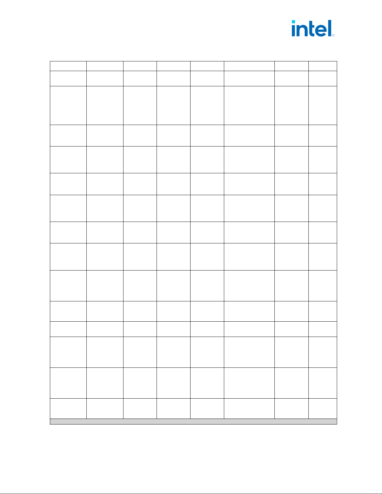
Symbol Parameter Segment Minimum Typical Maximum Unit Note
1
8P+12E
Core
IccMAX.App
(S Refresh
Processor)
Maximum
Processor
ICC .app
S Refresh-
Processor
Line (35W)
8P+16E/
8P+12E
Core
— — 140 A
4,5,6,7,1
1
IccMAX
(S Processor)
Maximum
Processor
ICC
S-Processor
Line (35W)
6P+8E Core
— — 120 A
4,5,6,7,1
1
IccMAX
(S Refresh
Processor)
Maximum
Processor
ICC
S Refresh -
Processor
Line (35W)
6P+8E Core
— — 120 A
4,5,6,7,1
1
IccMAX
(S Processor)
Maximum
Processor
ICC
S-Processor
Line (35W)
6P+4E Core
— — 100 A
4,5,6,7,1
1
IccMAX
(S Refresh
Processor)
Maximum
Processor
ICC
S Refresh -
Processor
Line (35W)
6P+4E Core
100 A
4,5,6,7,1
1
IccMAX
(S Processor)
Maximum
Processor
ICC
S-Processor
Line (35W)
4P+0E Core
— — 92 A
4,5,6,7,1
1
IccMAX
(S Refresh
Processor)
Maximum
Processor
ICC
S Refresh -
Processor
Line (35W)
4P+0E Core
92 A
4,5,6,7,1
1
Icc
TDC
Thermal
Design
Current (TDC)
for processor
VccCORE Rail
— — — VR_TDC A 9
TOB
VCC
Voltage
Tolerance
PS0,
PS1 ,PS2,
PS3
— — ±20 mV 3, 6, 8
TOB
VCC
+Ripple
Ripple
Tolerance
PS0, PS1,
PS2, PS3
— — -35 /+50 mV 3, 6, 8,16
DC_LL
Loadline slope
within the VR
regulation
loop
capability
S/S Refresh
- Processor
Line
(65W,125W)
0 — 1.1 mΩ
10,13,14,
18
DC_LL
Loadline slope
within the VR
regulation
loop
capability
S/S Refresh
-Processor
Line
( 35W)
0 — 1.7 mΩ
10,13,14,
18
AC_LL AC Loadline 3
S/S Refresh
Processor
Line
— — Same as DC LL mΩ 10,13,14
continued...
R
Electrical Specifications—Intel
®
Core
™
, Xeon
™
6300 And Xeon
™
E 2400 Processors
13
th
Generation Intel
®
Core
™
, Intel
®
Core
™
14
th
Generation, Intel
®
Core
™
Processor (Series 1) and (Series 2), Intel
®
Xeon
™
E
2400 Processor and Intel
®
Xeon
™
6300 Processor
May 2025 Datasheet, Volume 1 of 2
Doc. No.: 743844, Rev.: 015 191
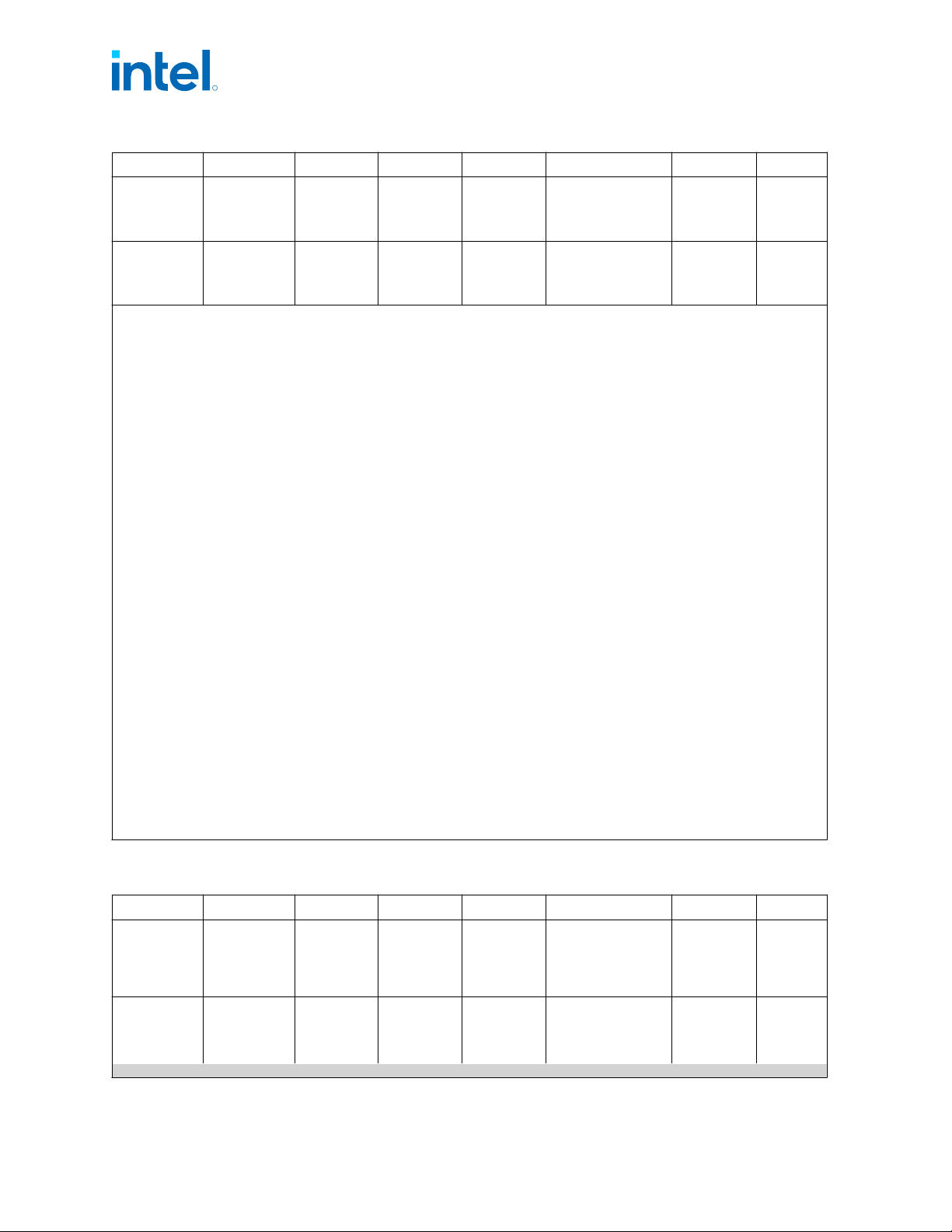
Symbol Parameter Segment Minimum Typical Maximum Unit Note
1
V_OVS
TDP_MAX/
virus_MAX
Maximum
Overshoot at
TDP/virus
mode
All Processor
Lines
— — 10 %
T_OVS_TDP_
MAX
Maximum
Overshoot at
TDP/virus
mode
All Processor
Lines
— — 500 us
Notes: 1. All specifications in this table are based on estimates and simulations or empirical data. These specifications will
be updated with characterized data from silicon measurements at a later date.
2. Each processor is programmed with a maximum valid voltage identification value (VID) that is set at
manufacturing and cannot be altered. Individual maximum VID values are calibrated during manufacturing such
that two processors at the same frequency may have different settings within the VID range. Note that this
differs from the VID employed by the processor during a power management event (Adaptive Thermal Monitor,
Enhanced Intel Speed-step Technology, or low-power states).
3. The voltage specification requirements are measured across Vcc_SENSE and Vss_SENSE as near as possible to
the processor. The measurement needs to be performed with a 20MHz bandwidth limit on the oscilloscope,
1.5pF maximum probe capacitance, and 1Ω minimum impedance. The maximum length of the ground wire on
the probe should be less than 5mm. Ensure external noise from the system is not coupled into the oscilloscope
probe.
4. Processor VccCORE VR to be designed to electrically support this current.
5. Processor VccCORE VR to be designed to thermally support this current indefinitely.
6. Long term reliability cannot be assured if tolerance, ripple, and core noise parameters are violated.
7. Long term reliability cannot be assured in conditions above or below Maximum/Minimum functional limits.
8. PSx refers to the voltage regulator power state as set by the SVID protocol.
9. Refer to Intel Platform Design Studio (iPDS) for the minimum, typical, and maximum VCC allowed for a given
current and Thermal Design Current (TDC).
10.LL measured at sense points.
11.Typical column represents IccMAX for commercial application it is NOT a specification - it's a characterization of
limited samples using limited set of benchmarks that can be exceeded.
12.Operating voltage range in steady state.
13.LL spec values should not be exceeded. If exceeded, power, performance and reliability penalty are expected.
14.Load Line (AC/DC) should be measured by the VRTT tool and programmed accordingly via the BIOS Load Line
override setup options. AC/DC Load Line BIOS programming directly affects operating voltages (AC) and power
measurements (DC). A superior board design with a shallower AC Load Line can improve on power, performance
and thermals compared to boards designed for POR impedance.
15.An IMVP9.1 controller to support VccCORE need to have an offset voltage capability and potentially VccCORE
output voltage (VID+Offset) may be higher than 1.5V.
16.Ripple can be higher if DC TOB is below 20mV, as long as Total TOB is within -35mV/+50mV.
17.S Processor Line K/KF/KS i9 SKUs and S Refresh Processor Line K/KF i9 SKUs - ICCMAX 400A is an optional
Extreme Power Delivery (PD) spec which opportunistically allows better multi-core performance based on
customer designs PD and if thermal headroom exists
18.1.1mOhm is the design limit for S-processor, achieving a lower design value will improve performance and
power efficiency
Table 78. Processor VCC
CORE
Active and Idle Mode DC Voltage and Current
Specifications (HX and HX Refresh Processor Lines)
Symbol Parameter Segment Minimum Typical Maximum Unit Note
1
Operating
Voltage
Voltage
Range for
Processor
Operating
Mode
HX /HX
Refresh -
Processor
Line
0 — 1.72 V
1,2,3,
7,12,15
IccMAX
(HX
Processor)
Maximum
Processor
ICC
HX-
Processor
Line (55W)
8P+16E/
— — 215 A
4,5,6,7,1
1
continued...
R
Intel
®
Core
™
, Xeon
™
6300 And Xeon
™
E 2400 Processors—Electrical Specifications
13
th
Generation Intel
®
Core
™
, Intel
®
Core
™
14
th
Generation, Intel
®
Core
™
Processor (Series 1) and (Series 2), Intel
®
Xeon
™
E
2400 Processor and Intel
®
Xeon
™
6300 Processor
Datasheet, Volume 1 of 2 May 2025
192 Doc. No.: 743844, Rev.: 015
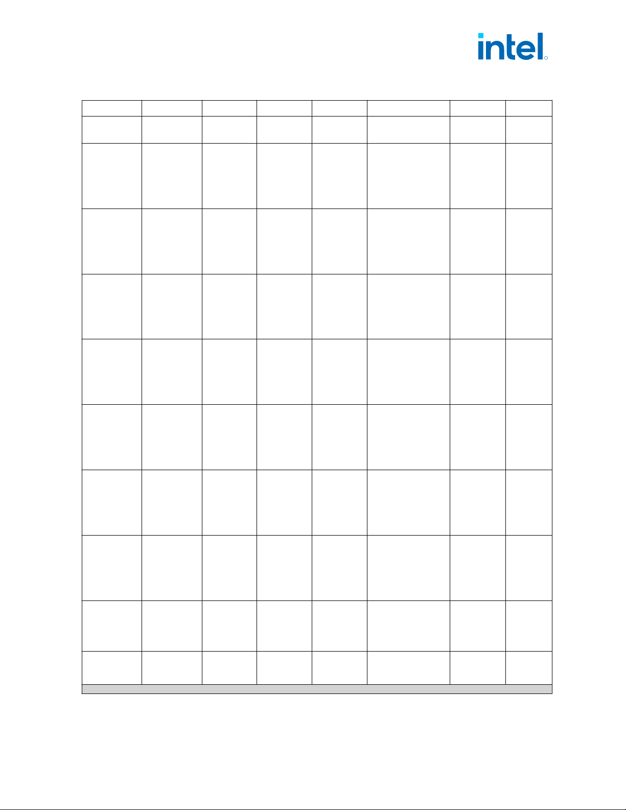
Symbol Parameter Segment Minimum Typical Maximum Unit Note
1
8P+12E/
8P+8E Core
IccMAX.App
(HX
Processor)
Maximum
Processor
ICC.app
HX-
Processor
Line (55W)
8P+16E/
8P+12E/
8P+8E Core
— — 175 A
4,5,6,7,1
1
IccMAX
(HX
Processor)
Maximum
Processor
ICC
HX-
Processor
Line (55W)
6P+8E/
6P+4E
Core
— — 160 A
4,5,6,7,1
1
IccMAX.App
(HX
Processor)
Maximum
Processor
ICC.app
HX-
Processor
Line (55W)
6P+8E/
6P+4E
Core
— — 130 A
4,5,6,7,1
1
IccMAX
(HX Refresh
Processor)
Maximum
Processor
ICC
HX Refresh-
Processor
Line (55W)
8P+16E/
8P+12E/
8P+8E Core
— — 215 A
4,5,6,7,1
1
IccMAX.App
(HX Refresh
Processor)
Maximum
Processor
ICC.app
HX Refresh-
Processor
Line (55W)
8P+16E/
8P+12E/
8P+8E Core
— — 175 A
4,5,6,7,1
1
IccMAX
(HX Refresh
Processor)
Maximum
Processor
ICC
HX Refresh-
Processor
Line (55W)
6P+8E/
6P+4E
Core
— — 160 A
4,5,6,7,1
1
IccMAX.App
(HX Refresh
Processor)
Maximum
Processor
ICC.app
HX Refresh-
Processor
Line (55W)
6P+8E/
6P+4E
Core
— — 130 A
4,5,6,7,1
1
Icc
TDC
Thermal
Design
Current (TDC)
for processor
VccCORE Rail
— — — VR_TDC A 9
TOB
VCC
Voltage
Tolerance
PS0,
PS1 ,PS2,
PS3
— — ±20 mV 3, 6, 8
continued...
R
Electrical Specifications—Intel
®
Core
™
, Xeon
™
6300 And Xeon
™
E 2400 Processors
13
th
Generation Intel
®
Core
™
, Intel
®
Core
™
14
th
Generation, Intel
®
Core
™
Processor (Series 1) and (Series 2), Intel
®
Xeon
™
E
2400 Processor and Intel
®
Xeon
™
6300 Processor
May 2025 Datasheet, Volume 1 of 2
Doc. No.: 743844, Rev.: 015 193