743844-015.pdf - 第65页
OS/HW Controlled P-states Enhanced Intel SpeedStep ® Technology Enhanced Intel SpeedStep ® T echnology enables OS to control and select P-state. For more information, refer to Enhanced Intel SpeedStep ® T echnology on pa…
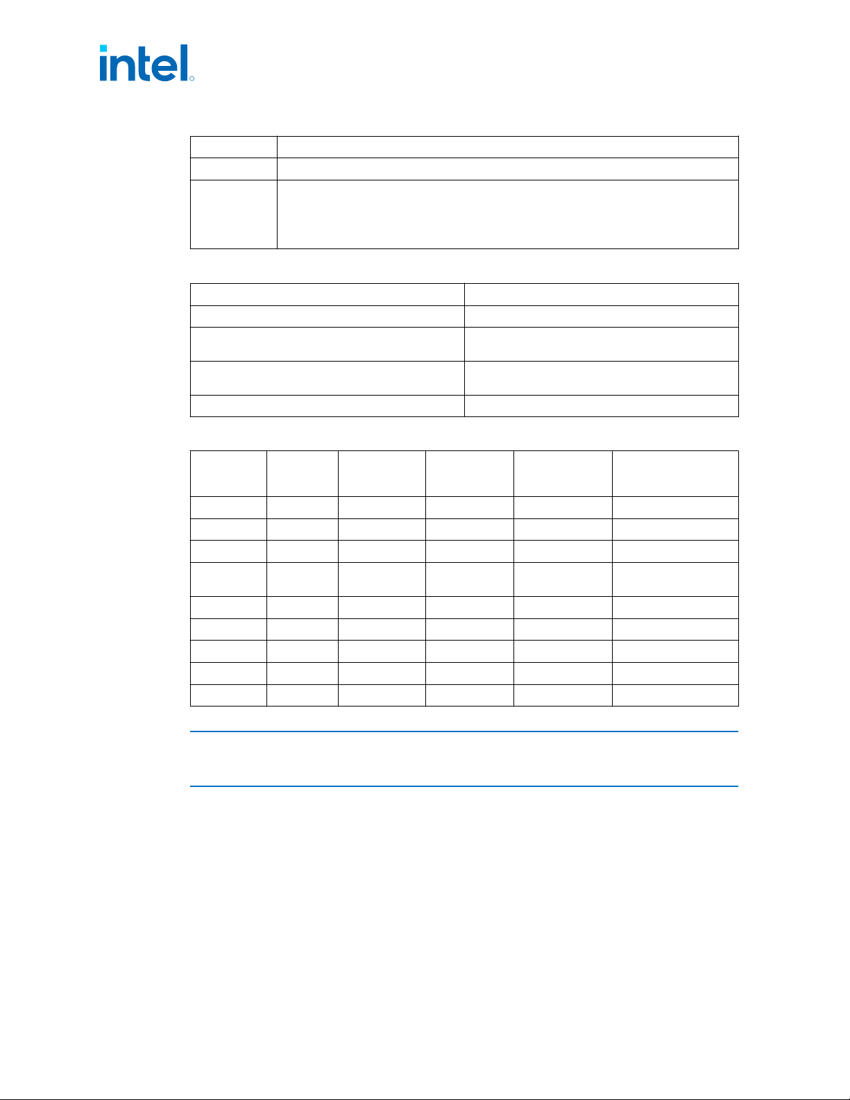
State Description
Here, SLP_S3, SLP_S4, and SLP_S5 are all active until a wake occurs.
G3
Mechanical OFF: System context not maintained. All power shut except for the RTC. No
“Wake” events are possible because the system does not have any power. This state occurs
if the user removes the batteries, turns off a mechanical switch, or if the system power
supply is at a level that is insufficient to power the “waking” logic. When system power
returns the transition will depend on the state just prior to the entry to G3.
Table 5. Integrated Memory Controller (IMC) States
State Description
Power-Up CKE asserted. Active mode.
Pre-Charge Power Down CKE de-asserted (not self-refresh) with all banks
closed.
Active Power Down CKE de-asserted (not self-refresh) with minimum
one bank active.
Self-Refresh CKE de-asserted using device self-refresh.
Table 6. G, S, and C Interface State Combinations
Global (G)
State
Sleep (S)
State
Processor
Package (C)
State
Processor
State
System Clocks Description
G0 S0 C0 Full On On Full On
G0 S0 C2
1
Deep Sleep On Deep Sleep
G0 S0 C3
1
Deep Sleep On Deep Sleep
G0 S0 C6
Deep Power
Down
On Deep Power Down
G0 S0 C8/C10 Off On Deeper Power Down
G1 S3 Power off Off Off, except RTC Suspend to RAM
G1 S4 Power off Off Off, except RTC Suspend to Disk
G2 S5 Power off Off Off, except RTC Soft Off
G3 N/A Power off Off Power off Hard off
NOTE
1. PkgC2/C3 are non-architectural: software cannot request to enter these states
explicitly. These states are intermediate states between PkgC0 and PkgC6.
Processor IA Core Power Management
While executing code, Enhanced Intel SpeedStep
®
Technology and Intel
®
Speed Shift
technology optimizes the processor’s IA core frequency and voltage based on
workload. Each frequency and voltage operating point is defined by ACPI as a P-state.
When the processor is not executing code, it is idle. A low-power idle state is defined
by ACPI as a C-state. In general, deeper power C-states have longer entry and exit
latencies.
3.2
R
Intel
®
Core
™
, Xeon
™
6300 And Xeon
™
E 2400 Processors—Power Management
13
th
Generation Intel
®
Core
™
, Intel
®
Core
™
14
th
Generation, Intel
®
Core
™
Processor (Series 1) and (Series 2), Intel
®
Xeon
™
E
2400 Processor and Intel
®
Xeon
™
6300 Processor
Datasheet, Volume 1 of 2 May 2025
64 Doc. No.: 743844, Rev.: 015
OS/HW Controlled P-states
Enhanced Intel SpeedStep
®
Technology
Enhanced Intel SpeedStep
®
Technology enables OS to control and select P-state. For
more information, refer to Enhanced Intel SpeedStep
®
Technology on page 49.
Intel
®
Speed Shift Technology
Intel
®
Speed Shift Technology is an energy efficient method of frequency control by
the hardware rather than relying on OS control. For more details, refer to Intel
®
Speed Shift Technology on page 50.
Low-Power Idle States
When the processor is idle, low-power idle states (C-states) are used to save power.
More power savings actions are taken for numerically higher C-states. However,
deeper C-states have longer exit and entry latencies. Resolution of C-states occurs at
the thread, processor IA core, and processor package level.
CAUTION
Long-term reliability cannot be assured unless all the Low-Power Idle States are
enabled.
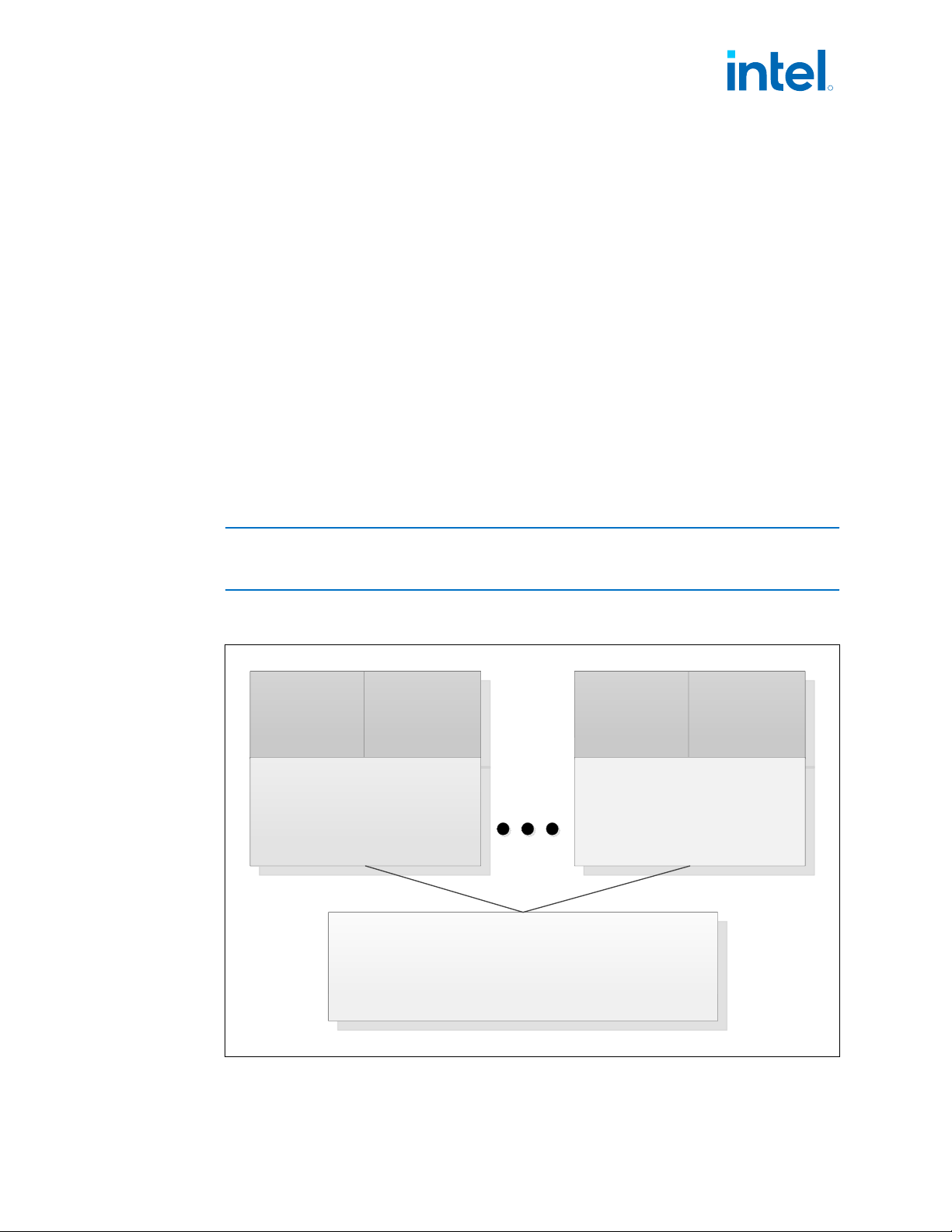
Figure 15. Idle Power Management Breakdown of the Processor IA Cores
Thread 0 Thread 1
Core 0 State
Thread 0 Thread 1
Core N State
Processor Package State
3.2.1
3.2.1.1
3.2.1.2
3.2.2
R
Power Management—Intel
®
Core
™
, Xeon
™
6300 And Xeon
™
E 2400 Processors
13
th
Generation Intel
®
Core
™
, Intel
®
Core
™
14
th
Generation, Intel
®
Core
™
Processor (Series 1) and (Series 2), Intel
®
Xeon
™
E
2400 Processor and Intel
®
Xeon
™
6300 Processor
May 2025 Datasheet, Volume 1 of 2
Doc. No.: 743844, Rev.: 015 65

While individual threads can request low-power C-states, power saving actions only
take place once the processor IA core C-state is resolved. processor IA core C-states
are automatically resolved by the processor. For thread and processor IA core C-
states, a transition to and from C0 state is required before entering any other C-state.
Requesting the Low-Power Idle States
The primary software interfaces for requesting low-power idle states are through the
MWAIT instruction with sub-state hints and the HLT instruction (for C1 and C1E).
However, the software may make C-state requests using the legacy method of I/O
reads from the ACPI-defined processor clock control registers, referred to as P_LVLx.
This method of requesting C-states provides legacy support for operating systems that
initiate C-state transitions using I/O reads.
For legacy operating systems, P_LVLx I/O reads are converted within the processor to
the equivalent MWAIT C-state request. Therefore, P_LVLx reads do not directly result
in I/O reads to the system. The feature, known as I/O MWAIT redirection, should be
enabled in the BIOS..
The BIOS can write to the C-state range field of the PMG_IO_CAPTURE MSR to restrict
the range of I/O addresses that are trapped and emulate MWAIT like functionality. Any
P_LVLx reads outside of this range do not cause an I/O redirection to MWAIT(Cx) like
the request. They fall through like a normal I/O instruction.
When P_LVLx I/O instructions are used, MWAIT sub-states cannot be defined. The
MWAIT sub-state is always zero if I/O MWAIT redirection is used. By default, P_LVLx
I/O redirections enable the MWAIT 'break on EFLAGS.IF’ feature that triggers a wake
up on an interrupt, even if interrupts are masked by EFLAGS.IF.
Processor IA Core C-State Rules
The following are general rules for all processor IA core C-states unless specified
otherwise:
• A processor IA core C-State is determined by the lowest numerical thread state
(such as Thread 0 requests C1E while Thread 1 requests C6 state, resulting in a
processor IA core C1E state). Refer to G, S, and C Interface State Combinations
table.
• A processor IA core transitions to C0 state when:
— An interrupt occurs
— There is an access to the monitored address if the state was entered using an
MWAIT/Timed MWAIT instruction
— The deadline corresponding to the Timed MWAIT instruction expires
• An interrupt directed toward a single thread wakes up only that thread.
• If any thread in a processor IA core is active (in C0 state), the core’s C-state will
resolve to C0.
• Any interrupt coming into the processor package may wake any processor IA core.
• A system reset re-initializes all processor IA cores.
3.2.3
3.2.4
R
Intel
®
Core
™
, Xeon
™
6300 And Xeon
™
E 2400 Processors—Power Management
13
th
Generation Intel
®
Core
™
, Intel
®
Core
™
14
th
Generation, Intel
®
Core
™
Processor (Series 1) and (Series 2), Intel
®
Xeon
™
E
2400 Processor and Intel
®
Xeon
™
6300 Processor
Datasheet, Volume 1 of 2 May 2025
66 Doc. No.: 743844, Rev.: 015