743844-015.pdf - 第29页
Table 3. Special Marks Mark Definition [] Brackets ([]) sometimes follow a ball, pin, registers or a bit name. These br ackets enclose a range of numbers, for example, T CP[2:0]_TXRX_P[1:0] may refer to four USB-C* pins …
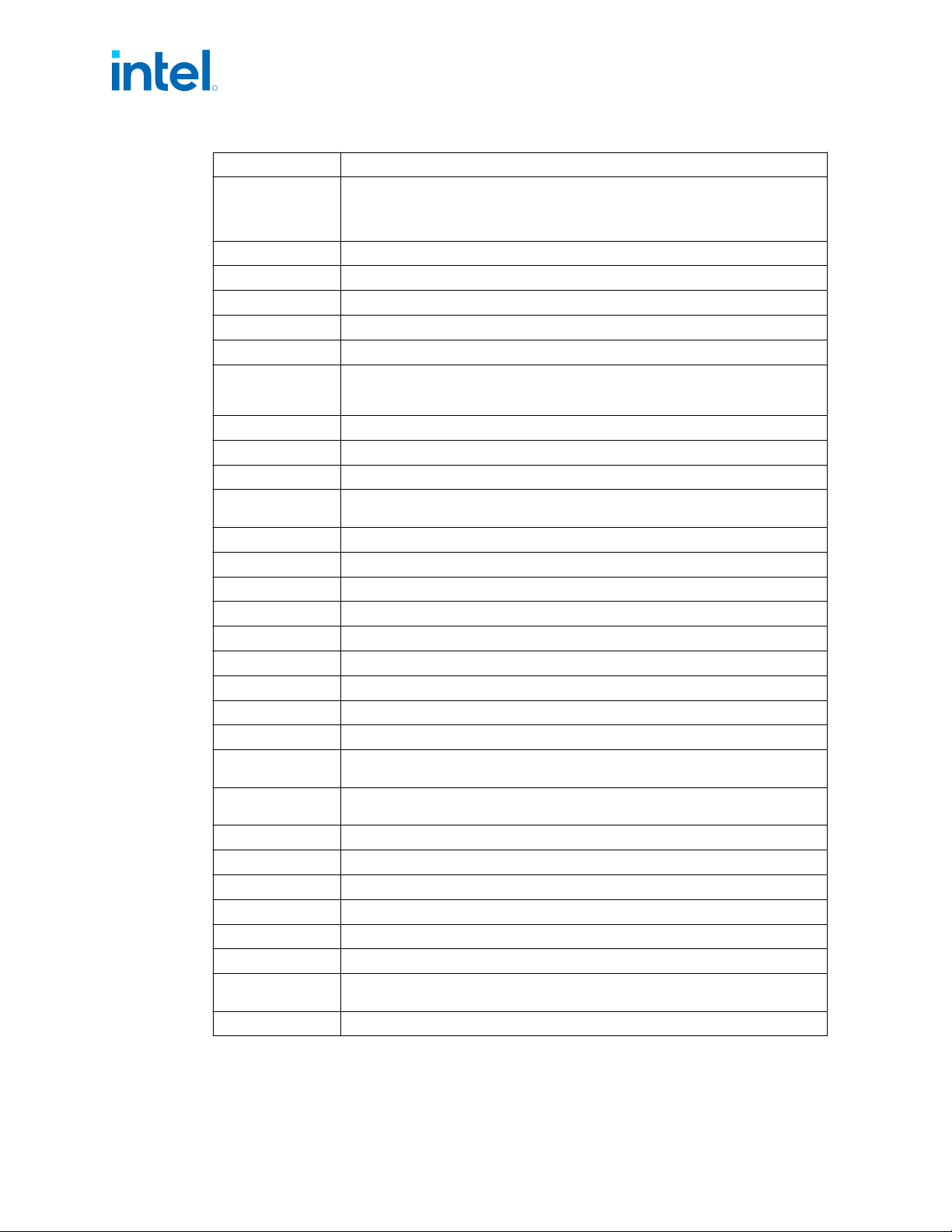
Term Description
PCH
Platform Controller Hub. The chipset with centralized platform capabilities including
the main I/O interfaces along with display connectivity, audio features, power
management, manageability, security, and storage features. The PCH may also be
referred to as “chipset”.
PECI Platform Environment Control Interface
PEG PCI Express* Graphics
PL1, PL2, PL3 Power Limit 1, Power Limit 2, Power Limit 3
PMIC Power Management Integrated Circuit
Processor The 64-bit multi-core component (package)
Processor Core
The term “processor core” refers to the Si die itself, which can contain multiple
execution cores. Each execution core has an instruction cache, data cache, and 256-
KB L2 cache. All execution cores share the LLC.
Processor Graphics Intel
®
Processor Graphics
PSR Panel Self-Refresh
PSx Power Save States (PS0, PS1, PS2, PS3, PS4)
Rank
A unit of DRAM corresponding to four to eight devices in parallel, ignoring ECC. These
devices are usually, but not always, mounted on a single side of a SoDIMM.
SCI System Control Interrupt. SCI is used in the ACPI protocol.
SDP Scenario Design Power
SHA Secure Hash Algorithm
SSC Spread Spectrum Clock
Storage Conditions Refer Package Storage Specifications on page 218.
STR Suspend to RAM
TAC Thermal Averaging Constant
TBT Thunderbolt
™
Interface
TCC Thermal Control Circuit
Processor Base
Power (a.k.a TDP)
Thermal Design Power
TTV Processor Base
Power (a.k.a TDP)
Thermal Test Vehicle TDP
V
CC
Processor Core Power Supply
V
CCGT
Processor Graphics Power Supply
V
CCSA
System Agent Power Supply
VLD Variable Length Decoding
VPID Virtual Processor ID
V
SS
Processor Ground
D0ix-states
USB controller power states ranging from D0i0 to D0i3, where D0i0 is fully powered
on and D0i3 is primarily powered off. Controlled by SW.
S0ix-states Processor residency idle standby power states.
R
Intel
®
Core
™
, Xeon
™
6300 And Xeon
™
E 2400 Processors—Introduction
13
th
Generation Intel
®
Core
™
, Intel
®
Core
™
14
th
Generation, Intel
®
Core
™
Processor (Series 1) and (Series 2), Intel
®
Xeon
™
E
2400 Processor and Intel
®
Xeon
™
6300 Processor
Datasheet, Volume 1 of 2 May 2025
28 Doc. No.: 743844, Rev.: 015
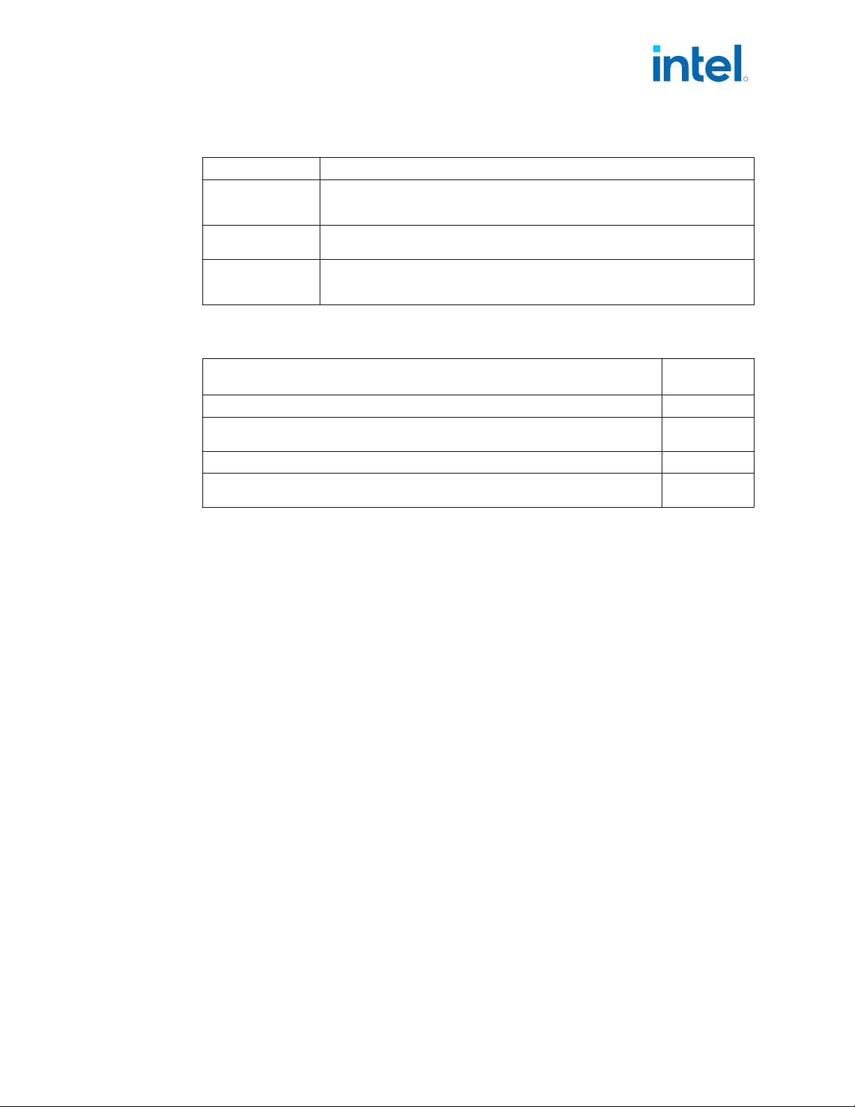
Table 3. Special Marks
Mark Definition
[] Brackets ([]) sometimes follow a ball, pin, registers or a bit name. These brackets
enclose a range of numbers, for example, TCP[2:0]_TXRX_P[1:0] may refer to four
USB-C* pins or EAX[7:0] may indicate a range that is 8 bits length.
_N / # / B A suffix of _N or # or B indicates an active low signal. For example, CATERR# _N
does not refer to a differential pair of signals such as CLK_P, CLK_N
0x000 Hexadecimal numbers are identified with an x in the number. All numbers are
decimal (base 10) unless otherwise specified. Non-obvious binary numbers have the
‘b’ enclosed at the end of the number. For example, 0101b
Related Documents
Document
Document
Number
Intel
®
700 Series Chipset Family Platform Controller Hub Datasheet, Volume 1 of 2 743835
Intel
®
700 Series Chipset Family On-Package Platform Controller Hub Datasheet, Volume 1
of 2
763122
13
th
Generation Intel
®
Core
™
Processors Datasheet, Volume 2 of 2 (for S-Processors) 743846
13
th
Generation Intel
®
Core
™
Processors Datasheet, Volume 2 of 2 (For P/PX/H/HX/U
Processors)
764981
1.10
R
Introduction—Intel
®
Core
™
, Xeon
™
6300 And Xeon
™
E 2400 Processors
13
th
Generation Intel
®
Core
™
, Intel
®
Core
™
14
th
Generation, Intel
®
Core
™
Processor (Series 1) and (Series 2), Intel
®
Xeon
™
E
2400 Processor and Intel
®
Xeon
™
6300 Processor
May 2025 Datasheet, Volume 1 of 2
Doc. No.: 743844, Rev.: 015 29
2.0 Technologies
This chapter provides a high-level description of Intel technologies implemented in the
processor.
The implementation of the features may vary between the processor SKUs.
Details on the different technologies of Intel processors and other relevant external
notes are located at the Intel technology web site: http://www.intel.com/technology/
NOTE
The last section of this chapter is dedicated to deprecated technologies. These
technologies are not supported in this processor but were supported in previous
generations.
Platform Environmental Control Interface
Platform Environmental Control Interface (PECI) is an Intel proprietary interface that
provides a communication channel between Intel processors and external components
such as Super IO (SIO) and Embedded Controllers (EC) to provide processor
temperature, Turbo, Assured Power (cTDP), and Memory Throttling Control
mechanisms and many other services. PECI is used for platform thermal management
and real-time control and configuration of processor features and performance.
NOTE
• PECI over eSPI is supported.
PECI Bus Architecture
The PECI architecture is based on a wired-OR bus that the clients (as processor PECI)
can pull up (with the strong drive).
The idle state on the bus is ‘0’ (logical low) and near zero (Logical voltage level).
NOTE
PECI supported frequency range is 3.2 kHz - 1 MHz.
The following figures demonstrate PECI design and connectivity:
• PECI Host-Clients Connection: While the host/originator can be third party PECI
host and one of the PECI client is a processor PECI device.
• PECI EC Connection.
2.1
2.1.1
R
Intel
®
Core
™
, Xeon
™
6300 And Xeon
™
E 2400 Processors—Technologies
13
th
Generation Intel
®
Core
™
, Intel
®
Core
™
14
th
Generation, Intel
®
Core
™
Processor (Series 1) and (Series 2), Intel
®
Xeon
™
E
2400 Processor and Intel
®
Xeon
™
6300 Processor
Datasheet, Volume 1 of 2 May 2025
30 Doc. No.: 743844, Rev.: 015