IPC-A-600H-2010 中文版 印制板的可接受性 (1).pdf - 第107页
This section identifies the acceptability characteristics in PTHs used in double-sided and multilayer rigid printed boards. Included in this sec- tion are photographic and illustrative depictions of PTH characteristics f…
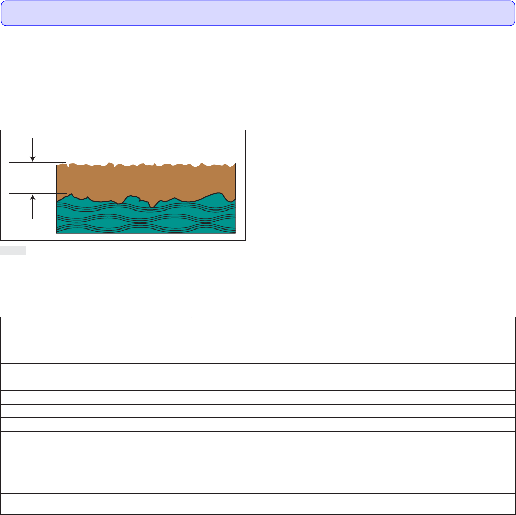
Minimum foil thickness (or conductor thickness) is the maximum continuous coplanar thickness that will conduct electrical current.
Individual scratches are included, but the saw-toothed shaped ‘‘dendritic’’ surface for metal-clad adhesion promotion is excluded from the
minimum foil thickness determination, as shown in Figure 324a.
最小铜箔厚度(或导体厚度)是传导电流的最大的连续共面厚度。
确定最小铜箔厚度时,包括个别的划痕,但用于加强金属箔粘结强度的锯齿状“树枝形”表面除外,如图324a所示。
The minimum internal layer foil thickness after processing shall be in accordance with Table 3-2.
加工后所有级别产品的最小内层铜箔厚度应当符合表3-2的规定:
Table 3-2 Internal Layer Foil Thickness after Processing
Weight
Absolute Cu Min. (IPC-4562
less 10% reduction) (µm) [µin]
Maximum Variable Processing
Allowance Reduction
1
(µm) [µin]
Minimum Final Finish
after Processing (µm) [µin]
重量
铜绝对最⼩值(⽐IPC-4562规定
值减少10%)(µm)[µin]
加⼯允许的最⼤减少量
1
(µm)[µin]
加⼯后成品导体最⼩厚度
(µm)[µin]
1/8 oz. [5.10] 4.60 [181] 1.50 [59] 3.1 [122]
1/4 oz. [8.50] 7.70 [303] 1.50 [59] 6.2 [244]
3/8 oz. [12.00] 10.80 [425] 1.50 [59] 9.3 [366]
1/2 oz. [17.10] 15.40 [606] 4.00 [157] 11.4 [449]
1 oz. [34.30] 30.90 [1,217] 6.00 [236] 24.9 [980]
2 oz. [68.60] 61.70 [2,429] 6.00 [236] 55.7 [2,193]
3 oz. [102.90] 92.60 [3,646] 6.00 [236] 86.6 [3,409]
4 oz. [137.20] 123.50 [4,862] 6.00 [236] 117.5 [4,626]
Above 4 oz.
[137.20]
IPC-4562 value
less 10% reduction
6.00 [236]
6 µm [236 µin] below minimum thickness of calcu-
lated 10% reduction of foil thickness in IPC-4562
4oz. [137.20]
以上
比IPC-4562规定值减少10% 6.00 [236]
比根据IPC-4562规定值减少10%
计算出的最小厚度少6µm[236µin]
Note 1. Process allowance reduction does not allow for rework processes for weights below
1
⁄
2
oz. For
1
⁄
2
oz. and above, the process allowance reduction allows
for one rework process.
Note 2. Additional platings that may be required for internal layer conductors shall be separately designated as a plating thickness requirement.
注1:对于重量小于1/2oz的铜箔,加工减少厚度值不允许进行返工制程。对于1/2oz及其以上的铜箔,加工减少厚度值允许进行一次返工制程。
注2:内层导体需要额外镀层时,应当单独规定其镀层厚度。
图324a
3.2 CONDUCTIVE PATTERNS – GENERAL(导电图形 – 总则)
3.2.4 Foil Thickness – Internal Layers(内层铜箔厚度)
Visual observations made on cross-sections only.
98 IPC-A-600H-20102010年4月

This section identifies the acceptability characteristics in PTHs used in double-sided and multilayer rigid printed boards. Included in this sec-
tion are photographic and illustrative depictions of PTH characteristics for both drilled and punched holes, with separate examples where
appropriate.
The test specimen shall be a representative coupon such as described in IPC-2221, a portion of the printed board being tested, or a whole
printed board if within size limits.
Sample holes should be selected at random. Vertical microsections, both parallel and perpendicular to a printed board edge, are recom-
mended. Horizontal microsectioning techniques may be used as the referee. Precise encapsulation and metallurgical techniques shall be used
to assure highly polished sections with correct part alignment and polishing to the mean of the hole diameter. The polished surface should be
etched after initial smear evaluation and just prior to plating thickness measurements.
The evaluation of all properties and requirements shall be performed on the thermally stressed test coupon and all requirements shall be met.
The coupons shall be tested after the printed board is exposed to all coating, final finish and thermal processing.
本节确定了刚性双面及多层印制板中镀覆孔的可接受性特性。包含在本节中的照片与示意图分别图示了钻孔镀覆孔或冲孔镀覆孔
的特性。
试样应当是具有代表性的如IPC-2221中描述的附连板、待测试印制电路板的一部分,如果尺寸在范围之内,也可用整块印制板。
样品孔应该随机选取。建议采用垂直显微切片,它与板边既平行又垂直。仲裁时,可采用水平的显微剖切技术。在制作时应当采
用精密的灌封与金相研磨技术,通过正确的调准,以确保获得高度的抛光剖面,同时使剖面抛光到孔径的中间。抛光的表面在作
初始去钻污评价后、镀层厚度测量前应该进行微蚀。
对所有属性与要求的评定应当在经过热应力测试后的附连板上进行,且应当满足所有要求。应当在印制板经过涂敷、最终涂覆和
加热工艺后测试附连板。
Methods of Inspection:
• Hole Size (method optional - IPC-TM-650, Method 2.2.7)
A. Optical
B. Document drill blank plug or plug gages
C. Tapered hole gage
Note: Hole gages must be cleaned and storage oil must be removed prior to use.
• Visual hole wall quality
A. Voids, nodules, etc., - locate with unaided eye, use up to 10X magnification for verification.
B. Discolorations, stains, etc., - use unaided eye and/or solderability tests.
检验⽅法:
• 孔径测量(可选⽅法 - 可参考IPC-TM-650测试⽅法2.2.7)
A. 光学法
B. 标准的钻针规或塞规
C. 锥形孔规
注: 孔规使用前必须洁净,并将防锈油脂擦拭干净。
• ⽬检孔壁质量
A. 空洞、结瘤等缺陷 - 以裸眼定位,再用高至10倍的放大镜进行验证。
B. 变色、污点等缺陷 - 采用以裸眼目视及/或进行可焊性测试。
3.3 PLATED-THROUGH HOLES – GENERAL(镀覆孔 – 总则)
Introduction(引⾔)
99IPC-A-600H-2010 2010年4月

Microsection:
• Plating thickness measurements
A. Encapsulated Microsection Examination (IPC-TM-650, Method 2.1.1 or Method 2.1.1.2): The average copper thickness should be
determined from three measurements, approximately equally spaced, on each side of the PTH. Do not measure in areas having isolated
imperfections such as voids, cracks or nodules. Small localized areas with plating thickness less than minimum requirement are evalu-
ated as voids.
B. Nondestructive Method: Micro-ohm Measurements (IPC-TM-650, Method 2.2.13.1): This technique may be used to measure the aver-
age copper thickness in PTH when properly standardized. The method has application to measurement of the minimum copper thick-
ness. Due to the dependence on uniform hole geometry this method may not be appropriate for measurement of punched PTHs. The
nondestructive feature and the speed and ease of measurement make this method useful in providing variable data for statistical process
control.
C. Plating Thickness: Minimum requirements are established in IPC-6010 series.
• Solderability
A lot sample or representative specimen should be subjected to a solderability test utilizing Methods B, B1, C, C1, D or D1 of IPC-J-STD-
003. The coating durability requirement should be pre-established. The PTHs should exhibit good wetting and capillary action.
显微切⽚:
• 镀层厚度测量
A. 灌封的显微切片检验(IPC-TM-650测试方法2.1.1或2.1.1.2):铜的平均厚度应该通过三个测量值来确定,在镀覆孔每侧壁
上大约等距离选取三个测试点。不要选用有孤立缺陷的区域,例如空洞、裂缝或结瘤等来测量镀铜厚度。小的局部区域镀
层厚度低于最小要求的,作为空洞来评定。
B. 非破坏性方法:微欧姆测量法(IPC-TM-650测试方法2.2.13.1):当此法经过适当的标定后,这种技术可用来测量镀覆孔铜
层的平均厚度。这种方法用来测量镀铜的最小厚度。由于此法与孔的形状的均匀性有关,因此不适合用于测定冲孔的镀覆
孔内的镀铜厚度。由于非破坏性的特点、快速且易于测量,使这种方法在为“统计过程控制”(SPC)提供计量数据时非
常有用。
C. 镀层厚度:IPC-6010系列标准建立了最小厚度要求。
• 可焊性
所选取的一批次具有代表性的样品应该采用ANSI/J-STD-003的B、B1、C、C1、D或D1测试方法进行可焊性测试。应该事先确
定涂覆层的耐久性要求。镀覆孔应该呈现良好的润湿和毛细作用。
3.3
PLA
TED-THROUGH HOLES – GENERAL(镀覆孔 – 总则)
Introduction (cont.)(引⾔(续))
100 IPC-A-600H-20102010年4月