IPC-A-600H-2010 中文版 印制板的可接受性 (1).pdf - 第148页
The transition zone is the area centered at the edge of the rigid portion from which the flexible portion extends. The inspection range is lim- ited to 3.0 mm [0.12 in], about the center of the transition, which is the e…

Acceptable - Class 1 (Adhesive)(可接受条件 - 1级)(粘接剂)
• The adhesive used to bond the stiffener does not reduce the solderable annular ring below the minimum solderable annular ring require-
ments.
• The total area of voids does not exceed 30% of the stiffener surface area.
• Each void does not exceed 2.5 mm [0.0984 in] in the longest dimension.
• 用于粘接增强板的粘接剂未使可焊孔环的宽度减少至低于最小环宽要求。
• 总的空洞区域未超过增强板表面面积的30%。
• 每个空洞的最长尺寸不超过2.5mm[0.0984in]。
Nonconforming - Class 1,2,3(不符合条件 - 1,2,3级)
• Defects either do not meet or exceed above criteria.
• 缺陷不符合或超出上述要求。
Test Method: Using a sharp instrument such as a scalpel or razor blade, cut approximately 10 mm [0.394 in] wide by 80 mm [3.15 in] long
through the flexible printed board to the stiffener so that approximately halfway through the peeling operation the sample will be perpendicu-
lar to the pull. Pull at a rate of 50 ± 6.3 mm/minute. Take readings at the beginning, middle, and end of the pull, and average the reading for
acceptability.
测试⽅法: 用一种锋利的工具,如解剖刀或剃须刀片,沿着挠性线路往增强板方向切割出一条宽约为10mm[0.394in]、长约为80
mm[3.15in]的粘接剂带,因此在剥离操作进行至约一半时样品将与剥离的方向成直角。剥离的速度为50±6.3mm/min。在剥离操作
的开始、中间和终止时记下测量数据,将测量数据平均从而确定可接受性。
4.1 FLEXIBLE AND RIGID-FLEX PRINTED BOARDS(挠性及刚挠性印制板)
4.1.5 Stiffener Bonding(增强板的粘接(续))
139IPC-A-600H-2010 2010年4月
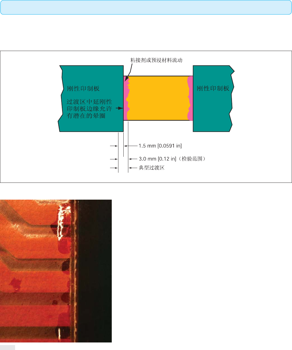
The transition zone is the area centered at the edge of the rigid portion from which the flexible portion extends. The inspection range is lim-
ited to 3.0 mm [0.12 in], about the center of the transition, which is the edge of the rigid portion.
过渡区以刚性段和挠性段的的边缘为中心。检验范围局限于过渡区的中心(即刚性段的边缘)附近3mm[0.12in]内。
Acceptable - Class 1,2,3(可接受条件 - 1,2,3级)
• Adhesive squeeze-out.
• Localized deformation of dielectric or conductors.
• Protruding dielectric material.
• 粘接剂挤出。
• 介质或导体的局部变形。
• 介质材料的突出。
Nonconforming - Class 1,2,3(不符合条件 - 1,2,3级)
• Defects either do not meet or exceed above criteria.
• 缺陷不符合或超出上述要求。
图416a
图416b
4.1 FLEXIBLE AND RIGID-FLEX PRINTED BOARDS(挠性及刚挠性印制板)
4.1.6 Transition Zone, Rigid Area to Flexible Area(刚性区域与挠性区域的过渡区)
140 IPC-A-600H-20102010年4月
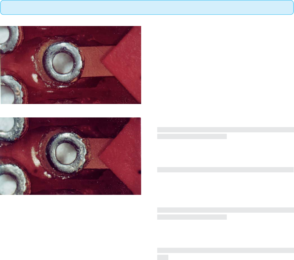
Target Condition - Class 1,2,3(⽬标条件 - 1,2,3级)
• Solder or plating on land covers all exposed metal and stops at
coverlay.
• Solder wicking or plating penetration does not extend into the
bend or flex transition area.
• 焊盘上的焊料或镀层覆盖了所有裸露的金属并止于覆盖层。
• 焊料芯吸或镀层渗透未延伸至弯曲或挠性过渡区域。
Acceptable - Class 3(可接受条件 - 3级)
• Solder wicking/plating penetration does not extend under cover-
lay more than 0.1 mm [0.004 in].
• Solder wicking or plating penetration does not extend into the
bend or flex transition area.
• Meets conductor spacing requirements.
• 焊料芯吸/镀层渗透在覆盖层下延伸不超过0.1mm[0.004in]。
• 焊料芯吸或镀层渗透没有延伸至弯曲或挠性过渡区域。
• 满足导体间距要求。
Acceptable - Class 2(可接受条件 - 2级)
• Solder wicking/plating penetration does not extend under cover-
lay more than 0.3 mm [0.012 in].
• Solder wicking or plating penetration does not extend into the
bend or flex transition area.
• Meets conductor spacing requirements.
• 焊料芯吸或镀层渗透在覆盖层下延伸不超过0.3mm[0.012
in]。
• 焊料芯吸或镀层渗透没有延伸至弯曲或挠性过渡区域。
• 满足导体间距要求。
图417a
图417b
4.1 FLEXIBLE AND RIGID-FLEX PRINTED BOARDS(挠性及刚挠性印制板)
4.1.7 Solder Wicking/Plating Penetration Under Coverlay(覆盖层下的焊料芯吸/镀层渗透)
141IPC-A-600H-2010 2010年4月