IPC-A-600H-2010 中文版 印制板的可接受性 (1).pdf - 第169页
The purpose of this section is to assist the reader in better understanding the importance of correct handling procedures in order to avoid dam- age and contamination during cleanliness testing. The following general rul…
This section covers acceptability criteria for flush printed boards. In flush printed boards, the surfaces, holes and other parameters for accept-
ability are the same as in standard single-and double-sided printed boards. This section covers the additional parameters that are important to
the evaluation of flush printed boards.
本节涵盖了齐平印制板的可接受性准则。在齐平印制板中,板表面、孔和其它性能的可接受性与常规的单面及双面印制板相同。
而本节所涉及的是对齐平印制板的评定有重要作用的附加参数。
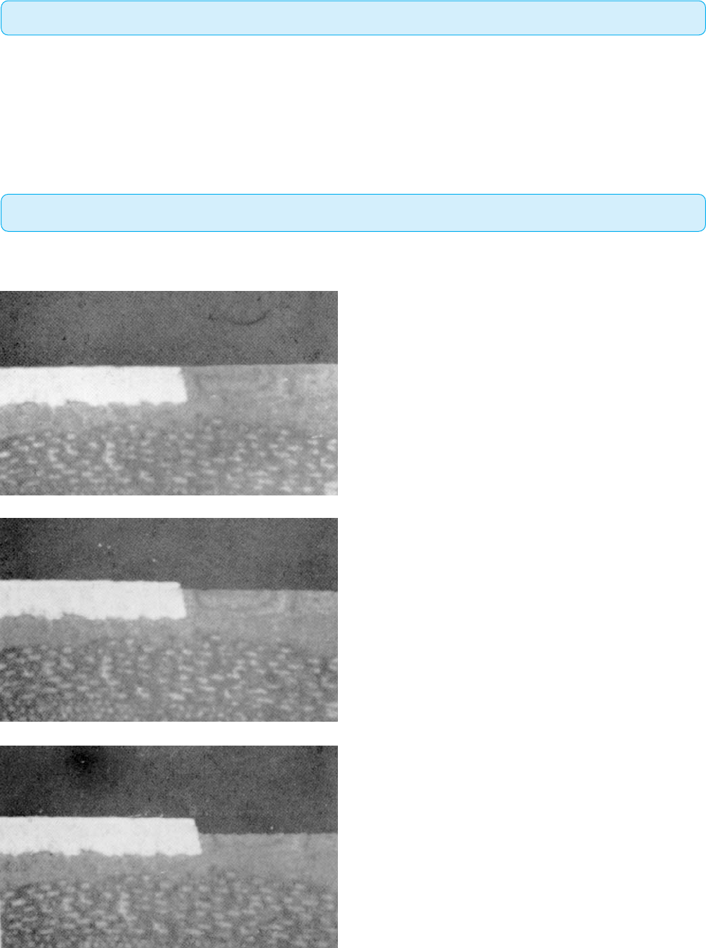
4.3.1 Flushness of Surface Conductor(表⾯导体的平整性)
The application of flush circuitry requires that the conductor surfaces and the base material be essentially in the same plane.
齐平电路要求导体表面和基材表面必需处在同一平面上。
Target Condition - Class 1,2,3(⽬标条件 - 1,2,3级)
• Conductor is flush to the base material or surrounding insulating
material surface.
• 导体与基材或所围绕的绝缘材料表面齐平。
Acceptable - Class 1,2,3(可接受条件 - 1,2,3级)
• Conductor is not flush but meets the minimum requirements.
• 导体虽不齐平,但满足最低要求。
Nonconforming - Class 1,2,3(不符合条件 - 1,2,3级)
• Defects either do not meet or exceed above criteria.
• 缺陷不符合或超出上述要求。
图431a
图431b
图431c
4.3 FLUSH PRINTED BOARDS(齐平印制板)
Introduction(引⾔)
160 IPC-A-600H-20102010年4月

The purpose of this section is to assist the reader in better understanding the importance of correct handling procedures in order to avoid dam-
age and contamination during cleanliness testing.
The following general rules minimize surface contaminants when handling printed boards:
1. Work stations should be kept clean and neat.
2. There should be no eating, drinking or use of tobacco products at the work station or other activities that are likely to cause contamination
of the printed board surfaces.
3. Hand creams and lotions containing silicone should not be used since they could result in solderability and other processing problems.
Specially formulated lotions are available.
4. Handling of printed boards by their edges is desirable.
5. Lint free cotton or disposable plastic gloves should be used when handling bare printed boards. Gloves should be changed frequently as
dirty gloves can cause contamination problems.
6. Unless special racks are provided, stacking printed boards without interleaving protection should be avoided. Cleanliness testing is used
to determine organic or inorganic, and ionizable or nonionizable contaminants.
The following are examples of the more common contaminants found on printed boards:
1. Flux residues
2. Particulate matter
3. Chemical salt residues
4. Fingerprints
5. Corrosion (oxides)
6. White residues
Due to the destructive nature of contaminants, it is recommended that cleanliness requirements of applicable procurement documentation be
adhered to.
The solvent resistivity shall be in accordance with IPC-6010 series unless otherwise specified. The specimens shall be tested for ionic con-
tamination in accordance with IPC-TM-650, Method 2.3.25 and 2.3.26.
本节的目的是帮助读者更好地理解正确持取方法的重要性,以避免在清洁度测试过程中导致损坏和污染。当持取印制板时,
下列通用规则可使表面污染最小化:
1. 工作台应该保持清洁与整洁。
2. 工作区不应该吃东西、喝饮料或吸烟,不应该作其它可能导致印制板面污染的活动。
3. 不应该使用含硅酮的护手霜和洗手液,因为它们会给印制板的可焊性和其它制程带来问题。可以采用特殊配方的洗手液。
4.
持取印制板时要求夹持板边。
5. 当持取裸板时,应该采用无尘棉织手套或一次性塑料手套。手套应该经常更换,因为脏的手套会导致污染问题。
6. 除非提供专门的架子,否则应该避免板子不加间隔保护而叠放。
下面是在印制板上常见污染的例子:
1. 助焊剂残留物
2. 颗粒物
3. 化学盐类残留物
4. 手指印
5. 腐蚀(氧化物)
6. 白色残留物
由于污染物具有破坏性,建议遵守适用采购文件的清洁度要求。
除非另有规定,清洗溶剂的电阻率应当符合IPC-6010系列文件的要求。应当按照IPC-TM-650测试方法2.3.25和2.3.26测试样本的
离子污染。
5
CLEANLINESS TESTING(清洁度测试)
Introduction(引⾔)
161IPC-A-600H-2010 2010年4月
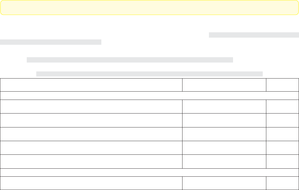
This section describes the methods and requirements for solderability testing. Solderability of printed boards verifies the state of the printed
board expected during assembly. Solderability testing is performed on both the surface and PTHs. IPC-J-STD-003 describes in detail the dif-
ferent solderability tests as shown in Table 5-1:
本节介绍了可焊性测试的方法和要求。印制板的可焊性测试是为了验证印制板在组装时的可焊性。在板的两面和镀覆孔内实施可
焊性测试。IPC-J-STD-003详细地介绍了各种不同的可焊性测试,表5-1列出了各种可焊性测试方法。
Table 5-1 Test Method Selection within IPC-J-STD-003(表5-1 IPC-J-STD-003中的测试⽅法选择)
Test Method
(测试⽅法)
Applies to Surface Features
(适⽤于表⾯特征)
PTHs
(镀覆孔)
Tests with Visual Assessment Criteria(具有外观评定标准的测试)
A – Edge Dip Test / A1 – Edge Dip Test
A–边缘浸焊测试 /A1–边缘浸焊测试
X
N/A
不适用
B – Rotary Dip Test / B1 – Rotary Dip Test
B–摆动浸焊测试 /B1–摆动浸焊测试
X (Solder Source Side Only)
X(仅在焊接终止面)
X
C – Solder Float Test / C1 – Solder Float Test
C–浮焊测试 /C1–浮焊测试
X (Solder Source Side Only)
X(仅在焊接终止面)
X
D – Wave Solder Test / D1 – Wave Solder Test
D–波峰焊测试 /D1–波峰焊测试
X (Solder Source Side Only)
X(仅在焊接终止面)
X
E – Surface Mount Simulation Test / E1 – Surface Mount Simulation Test
E–表面贴装模拟测试 /E1–表面贴装模拟测试
X
N/A
不适用
Tests with Force Measurement Criteria(具有⼒度测量标准的测试)
F
–
Wetting Balance Test / F1 – Wetting Balance Test
F–润湿平衡测试 /F1–润湿平衡测试
XX
Along with the solderability method, the user shall specify as part of the purchase order agreement, the required coating durability. The fol-
lowing are guidelines for determining the needed level of coating durability, not product performance classes. Durability conditioning and
solderability testing shall be performed per IPC-J-STD-003.
Coating Durability categories:
Category1–Minimum Coating Durability; intended for printed boards which will be soldered within 30 days from the time of manufac-
ture and are likely to experience minimum thermal exposures.
Category2–Average Coating Durability; intended for printed boards likely to experience storage up to six months from the time of manu-
facture and moderate thermal or solder exposures.
Category3–Maximum Coating Durability; intended for printed boards likely to experience long storage (over six months) from the time
of manufacture, and may experience severe thermal or solder processing steps, etc. It should be recognized that there may be a cost premium
or delivery delay associated with printed boards ordered to this durability level.
The test specimen shall be a representative coupon, a portion of the printed board being tested, or a whole board if within size limits, such
that a immersion depth defined in the individual method is possible. Sample holes should be selected at random.
除了可焊性测试方法以外,用户还应当在采购协议中规定所要求的涂覆层耐久性。下面是确定所需涂覆层耐久性类型的指南,但
它不是产品性能等级。应当按IPC/J-STD-003的规定完成加速老化和可焊性测试。
涂覆层耐久性分类:
1类 – 最低水平的涂覆层耐久性。指制造完工后30天内要焊接的印制板,可能会暴露于最低程度的热环境中。
2类 – 一般水平的涂覆层耐久性。指制造完工后经过6个月以内贮存的印制板,可能会暴露于中等程度的热或焊接环境中。
3类 – 最高水平的涂覆层耐久性。指制造完工后经过长时间(6个月以上)贮存的印制板,可能会经历严苛的热环境或焊接工序
等。但应该注意到,采购该类印制板会增加额外成本、延长交货期。
测试样品应当为具有代表性的测试附连板、被测试印制板的一部分,或如果尺寸在限定范围内、以至可以达到测试方法规定的浸
焊深度,也可用整块印制板。试样的样品孔应该随机抽取。
5.1
SOLDERABILITY
TESTING(可焊性测试)
Introduction(引⾔)
162 IPC-A-600H-20102010年4月