IPC-A-600H-2010 中文版 印制板的可接受性 (1).pdf - 第132页
Nonconforming - Class 1,2,3 (不符合条件 - 1,2,3级) • Defects either do not meet or exceed above criteria. • 缺陷不符合或 超 出上述要求。 图 3317c 3.3 PLA TED-THROUGH HOLES – GENERAL (镀覆孔 – 总 则) 3.3.17 Cap Plating of Filled Holes (cont.) (填塞…
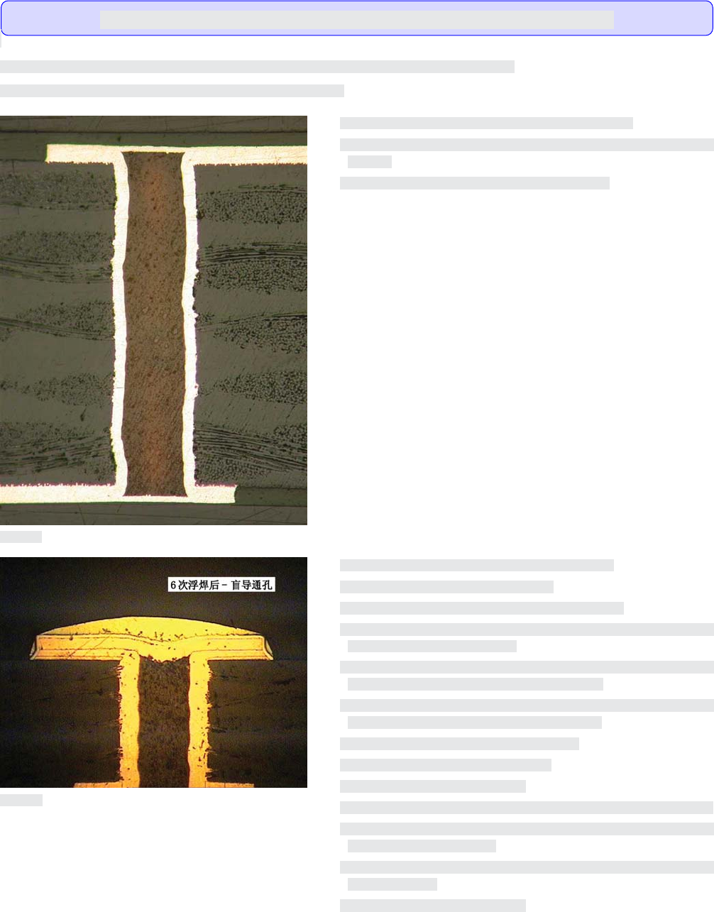
When copper cap plating of filled holes is specified by the master drawing the following shall apply.
当布设总图规定用铜盖覆电镀填塞孔时,应当采用以下要求。
Target Condition - Class 1,2,3(⽬标条件 - 1,2,3级)
• Copper surface is planar with no protrusion (bump) and/or depression
(dimple)
• 铜表面平整,无凸起(凸块)和凹陷(凹坑)。
Acceptable - Class 1,2,3(可接受条件 - 1,2,3级)
• Separation of copper cap to fill material.
• No separation of the cap plating to underlying plating.
• Cap protrusion (bump) and/or depression (dimple) meets the dimen-
sional requirements in IPC-6012.
• Fill material within the blind via shall be planar with the surface within
± 0.076 mm [0.003 in] unless otherwise specified.
• When cap plating is specified, fill material within the blind via shall
meet the dimple/bump requirements of IPC-6012.
• No voids in the cap plating over the resin fill.
• 允许铜盖覆层与孔填塞材料的分离。
• 盖覆镀层与底层镀层没有分离。
• 盖覆的凸起(凸块)和凹陷(凹坑)满足IPC-6012中的尺寸要求。
• 除 非 另 有规定,盲导通孔内的填塞材料与表面的平整度应当在
+/-0.076mm[0.003in]以内。
• 当规定盖覆电镀时,盲孔内的填塞材料应当满足IPC-6012中的凹
陷和凸起要求。
• 填塞树脂上的盖覆镀层无空洞。
图3317b
图3317a
3.3 PLATED-THROUGH HOLES – GENERAL(镀覆孔 – 总则)
3.3.17 Cap Plating of Filled Holes(填塞孔的盖覆电镀)
Visual observations made on cross-sections only.(仅对显微切片进行目检观察。)
123IPC-A-600H-2010 2010年4月
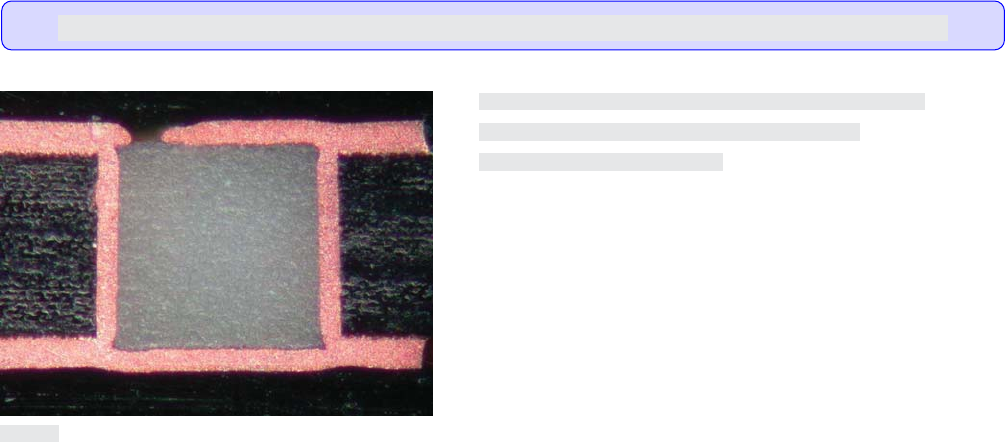
Nonconforming - Class 1,2,3(不符合条件 - 1,2,3级)
• Defects either do not meet or exceed above criteria.
• 缺陷不符合或超出上述要求。
图3317c
3.3 PLATED-THROUGH HOLES – GENERAL(镀覆孔 – 总则)
3.3.17 Cap Plating of Filled Holes (cont.)(填塞孔的盖覆电镀(续))
Visual observations made on cross-sections only.(仅对显微切片进行目检观察。)
124 IPC-A-600H-20102010年4月

This section identifies the acceptability characteristics for drilled PTHs. Although only two characteristics are identified (burrs and nailhead-
ing), good drilling is essential for a good PTH. The drilled hole wall should be smooth and free of burrs, delamination, burning, crushed insu-
lation, and protruding fibers. The hole should be perpendicular, round and not tapered. A poorly drilled hole may cause other problems that
have been described and characterized in other sections of this document. These problems are:
• Rough plating
• Nodules
• Plating voids
• Thin plating
• Plating cracks (hole wall, corner)
• Wicking (excessive)
• Hole size reduction
• Pink ring
• Blow holes in soldering
• Skip plating
The physical appearance of a particular hole will be affected by one or more of the following variables:
• Drill point angle
• Drill rotation speed
• Drill feed rate
• Drill sharpness
Nailheading is a condition which may develop during the drilling operation. Worn drills, improper speeds and feeds, and/or soft back up and
entry materials usually cause nailheading. The condition is acceptable for all classes.
本节旨在说明钻孔镀覆孔的可接受特性。虽然仅规定了两种特性(毛刺和钉头),但良好的钻孔是优质镀覆孔的关键。钻孔的孔
壁应该平滑且没有毛刺、分层、烧焦、破碎绝缘物及突出的纤维等。孔应该垂直、圆而非锥形。差的钻孔可能引起的其它许多问
题,这些已经在本文件的其它章节中进行了描述与说明。这些问题是:
• 镀层粗糙
• 结瘤
• 镀层空洞
• 镀层过薄
• 镀层裂缝(孔壁、拐角)
• 芯吸(过度)
• 孔径减小
• 粉红环
• 焊接时出现气孔
• 跳镀
个别孔的物理外观会受以下一项或多项变量的影响:
• 钻尖角度;
• 钻头转速;
• 钻头进给速率;
• 钻头锐利度。
钉头是钻孔过程中可能产生的一种状况。钉头通常是由于钻头磨损、不适当的转速及进给速率,和(或)软的垫板、盖板材料等
造成的。这种情况对所有级别产品均是可接受的。
3.4
PLATED-THROUGH HOLES – DRILLED(镀覆孔 – 钻孔)
Introduction(引⾔)
125IPC-A-600H-2010 2010年4月