IPC-A-600H-2010 中文版 印制板的可接受性 (1).pdf - 第150页
Acceptable - Class 1 (可接受条件 - 1级) • Solder wicking/plating penetration does not extend under cover- lay more than 0.5 mm [0.020 in]. • Solder wicking or plating penetration does not extend into the bend or flex transitio…
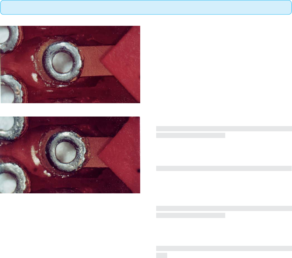
Target Condition - Class 1,2,3(⽬标条件 - 1,2,3级)
• Solder or plating on land covers all exposed metal and stops at
coverlay.
• Solder wicking or plating penetration does not extend into the
bend or flex transition area.
• 焊盘上的焊料或镀层覆盖了所有裸露的金属并止于覆盖层。
• 焊料芯吸或镀层渗透未延伸至弯曲或挠性过渡区域。
Acceptable - Class 3(可接受条件 - 3级)
• Solder wicking/plating penetration does not extend under cover-
lay more than 0.1 mm [0.004 in].
• Solder wicking or plating penetration does not extend into the
bend or flex transition area.
• Meets conductor spacing requirements.
• 焊料芯吸/镀层渗透在覆盖层下延伸不超过0.1mm[0.004in]。
• 焊料芯吸或镀层渗透没有延伸至弯曲或挠性过渡区域。
• 满足导体间距要求。
Acceptable - Class 2(可接受条件 - 2级)
• Solder wicking/plating penetration does not extend under cover-
lay more than 0.3 mm [0.012 in].
• Solder wicking or plating penetration does not extend into the
bend or flex transition area.
• Meets conductor spacing requirements.
• 焊料芯吸或镀层渗透在覆盖层下延伸不超过0.3mm[0.012
in]。
• 焊料芯吸或镀层渗透没有延伸至弯曲或挠性过渡区域。
• 满足导体间距要求。
图417a
图417b
4.1 FLEXIBLE AND RIGID-FLEX PRINTED BOARDS(挠性及刚挠性印制板)
4.1.7 Solder Wicking/Plating Penetration Under Coverlay(覆盖层下的焊料芯吸/镀层渗透)
141IPC-A-600H-2010 2010年4月
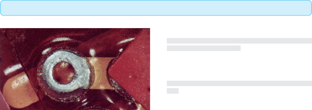
Acceptable - Class 1(可接受条件 - 1级)
• Solder wicking/plating penetration does not extend under cover-
lay more than 0.5 mm [0.020 in].
• Solder wicking or plating penetration does not extend into the
bend or flex transition area.
• Meets conductor spacing requirements.
• 焊 料 芯吸 或 镀层渗 透在覆盖层 下延伸不超过0.5mm[0.012
in]。
• 焊料芯吸或镀层渗透没有延伸至弯曲或挠性过渡区域。
• 满足导体间距要求。
Nonconforming - Class 1,2,3(不符合条件 - 1,2,3级)
• Defects either do not meet or exceed above criteria.
• 缺陷不符合或超出上述要求。
图417c
4.1 FLEXIBLE AND RIGID-FLEX PRINTED BOARDS(挠性及刚挠性印制板)
4.1.7 Solder Wicking/Plating Penetration Under Coverlay(覆盖层下的焊料芯吸/镀层渗透(续))
142 IPC-A-600H-20102010年4月
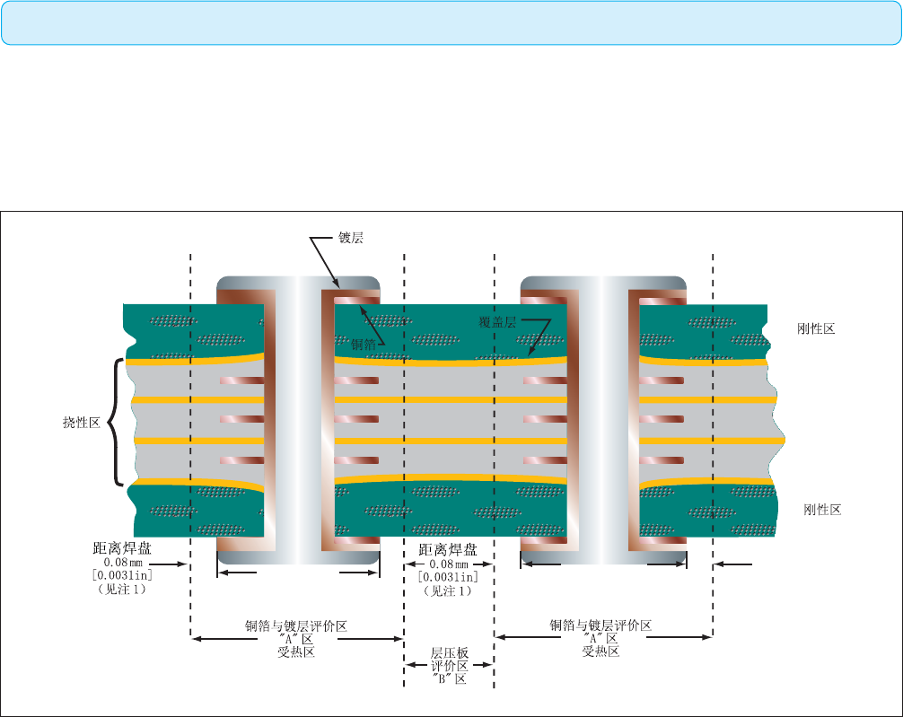
This section shows the voids and cracks that may be present in flexible or rigid-flex printed boards. The requirements for the flexible portion
differ from the rigid-flex portion and are defined in the text even though only a rigid-flex section is shown.
本节讨论挠性或刚挠印制板上可能出现的空洞和裂缝。挠性部分的要求与刚挠印制部分有所不同,尽管只图示出了刚挠印制线路
部分,但正文对挠性印制线路作了规定。
Target Condition(⽬标条件)
• No laminate voids or cracks.
• 无层压板空洞或裂缝。
图418a
Notes:
1. The thermal zone extends 0.08 mm [0.0031 in] beyond the end of the land that is most radially extended.
2. Laminate anomalies or imperfections in Zone A areas are not evaluated on specimens, which have been exposed to thermal stress or rework
simulation.
3. Multiple voids or cracks between PTHs in the flex area and in the same plane shall not have combined length exceeding the limit.
注:
1. 受热区是指从内层或外层中最靠外的焊盘边缘向层压板延伸0.08mm[0.0031in]所包含的区域。
2. 对已经经受热应力测试或模拟返工测试的试样,A区内出现的层压板异常或瑕疵不作评价。
3. 在挠性区域内同一层面上镀覆孔间的多个空洞或裂缝,其累积长度不应当超出规定限值。
}
}
4.1 FLEXIBLE AND RIGID-FLEX PRINTED BOARDS(挠性及刚挠性印制板)
4.1.8 Laminate Integrity(层压板完整性)
143IPC-A-600H-2010 2010年4月