LCX_UserManual_en_08_1.pdf - 第107页
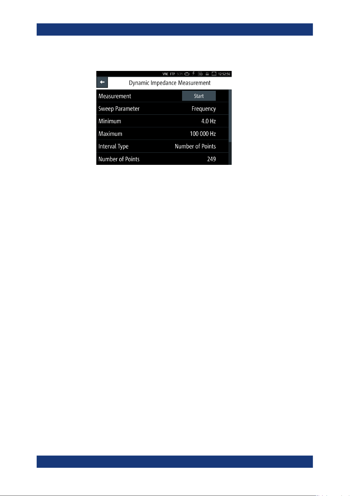
Instrument functions R&S ® LCX Series 107 User Manual 1 179.2260.02 ─ 08 2. In the "Functions" tab, select "Dynamic Impedance Measurement". Figure 8-24: Dynamic impedance measurement menu This men…

Instrument functions
R&S
®
LCX Series
106User Manual 1179.2260.02 ─ 08
3. Select "Mode" > "Span".
A selection editor opens.
4. Select "Span".
5. Confirm you selection.
6. To set the time parameters for the selected mode:
a) Select "Interval"
b) In the on-screen keypad, enter time and unit, e.g. "0.1 s".
c)
Confirm with
.
d) Proceed the same way to set the duration and the start time.
Note: For the start time, the R&S LCX opens a selection editor, providing date set-
tings, and steps to a second editor for setting the start time at the selected date.
The R&S LCX starts logging at the defined date and time, and stops after the dura-
tion time has elapsed. It generates the filename and saves the logging data in the
specified memory location, see "Selecting the memory location" on page 105.
To configure the other logging modes, proceed the same way.
8.8.4 Dynamic impedance measurement
Option: R&S LCX-K106
The dynamic impedance measurement function allows you to acquire a measurement
series from the currently selected measurement pairs by sweeping the test signal.
The R&S LCX sweeps through the range of test signal parameter values and records
the acquired measurement data in a log file.
After completing a sweep cycle, the R&S LCX displays the recorded measurement
graphically in the logging chart viewer. See Section 8.8.2, "Logging chart viewer",
on page 97.
Interactions and characteristics
The R&S LCX calculates the dynamic impedance measurement parameters according
to the test signal settings. I.e., changing the frequency, range or voltage of the test sig-
nal impacts the sweep parameter values, ranges and limits.
8.8.4.1 Dynamic impedance measurement settings
Option: R&S LCX-K106
Access:
1. Press the [settings] key at the front panel.
Specific instrument functions
Instrument functions
R&S
®
LCX Series
107User Manual 1179.2260.02 ─ 08
2. In the "Functions" tab, select "Dynamic Impedance Measurement".
Figure 8-24: Dynamic impedance measurement menu
This menu provides the parameters to configure the test signal for dynamic impe-
dance measurement.
The required remote commands are described in Section 11.8, "DIMeasure subsys-
tem", on page 198.
How to: see Section 8.8.4.2, "Using the dynamic impedance measurement function",
on page 109
Measurement.............................................................................................................. 107
Sweep Parameter....................................................................................................... 107
Minimum......................................................................................................................108
Maximum.....................................................................................................................108
Interval Type................................................................................................................108
Step Size.....................................................................................................................108
Number of Points........................................................................................................ 108
Abort............................................................................................................................109
Measurement
Starts the dynamic impedance measurement sweep.
The R&S LCX displays a progress dialog until the measurement is complete, see
"Measuring in dynamic impedance measurement mode" on page 109.
Remote command:
DIMeasure:EXECute on page 200
Sweep Parameter
Opens a selection editor to determine the measurement signal parameter that changes
during the entire measurement process.
The R&S LCX varies this parameter within the range between Minimum and Maximum
in constant steps continuously. You can define the increment with the Interval type and
the corresponding settings parameter, either Step Size or "Number of Points"
on page 108.
Specific instrument functions

Instrument functions
R&S
®
LCX Series
108User Manual 1179.2260.02 ─ 08
"Test Signal Voltage"
Varies the test signal voltage level during the measurement process.
"Frequency"
Varies the frequency of the test signal.
"Voltage Bias"
Varies the voltage bias value.
"Current Bias"
Varies the voltage bias value.
Remote command:
DIMeasure:SWEep:PARameter on page 202
Minimum
Sets the first value of the range used for the selected sweep parameter.
Remote command:
DIMeasure:SWEep:MINimum on page 201
Maximum
Sets the last value of the range used for the selected sweep parameter.
Remote command:
DIMeasure:SWEep:MAXimum on page 201
Interval Type
Opens a selection editor to select the mode how the instrument calculates the width or
time between the recorded sweep parameters within the measurement range (Min/
Max).
"Step Size"
Uses the interval between one sweep parameter value to the next,
set with Step Size.
"Number of Points"
Uses the number of values within the range of minimum and maxi-
mum sweep parameter settings, set with Number of Points.
Remote command:
DIMeasure:INTerval:TYPE on page 201
Step Size
Sets the interval between each sweep step within the measurement range Min/Max).
Depending on the selected sweep parameter, the R&S LCX provides the correspond-
ing value and unit.
"xx V"
For Sweep Parameter > Test Signal Voltage or Voltage Bias, sets the
increment in V.
"xx Hz"
For Sweep Parameter > Frequency, sets the time interval in Hz.
"xx A"
For Sweep Parameter > Current Bias, sets the increment in A.
Remote command:
DIMeasure:INTerval:STEPsize on page 201
Number of Points
Sets the number of measurement points within the measurement range (Min/Max).
Remote command:
DIMeasure:INTerval:POINts on page 200
Specific instrument functions