LCX_UserManual_en_08_1.pdf - 第73页
Instrument functions R&S ® LCX Series 73 User Manual 1 179.2260.02 ─ 08 <measurement pair> Selects the measurement parameter pairs. Depending on the type of component sample, the R&S LCX adjusts the list of…
Instrument functions
R&S
®
LCX Series
72User Manual 1179.2260.02 ─ 08
Note: The trigger icon also turns white during the measurement cycle. If you
have set a delay time, the trigger icon turns yellow until the delay time is elapsed.
5. Optionally, configure the next working point.
6. Repeat the steps until you have executed the measurement at all working points.
8.2 Display mode
The R&S LCX indicates the measurement results numerically and graphically.
Based on the measured values, the instrument calculates and derives the non-measur-
able parameters for display.
8.2.1 Display mode settings
Access:
1. To select the measurement result display, press the [home] key at the front panel.
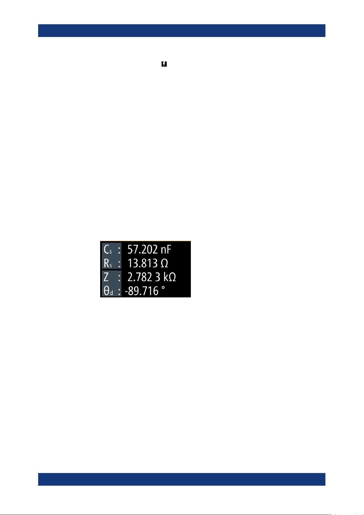
The numeric display shows the readings of four-measurement pairs by default.
Figure 8-1: Four measurement pairs display
2. Press the [Display Mode] key.
3. Pressing the key repeatedly, toggles between this view, the view with one mea-
surement pair and the graphical view.
Note: You can also access the graphical display in the "Functions" tab, see Sec-
tion 8.8, "Specific instrument functions", on page 93.
The results display shows the measurement results of the currently selected
parameters. The softkeys enable you to select the parameters for display accord-
ing to your measurement.
The required remote commands are described in: Section 11.11, "FUNCtion sub-
system", on page 209
How to: see Section 8.2.2, "Configuring the main view", on page 73.
<measurement pair>.....................................................................................................73
<measurement accuracy>.............................................................................................73
Display mode
Instrument functions
R&S
®
LCX Series
73User Manual 1179.2260.02 ─ 08
<measurement pair>
Selects the measurement parameter pairs.
Depending on the type of component sample, the R&S LCX adjusts the list of parame-
ters automatically.
Remote command:
FUNCtion:IMPedance[:TYPE][:PRIMary] on page 212
FUNCtion:IMPedance:TYPE:SECondary on page 213
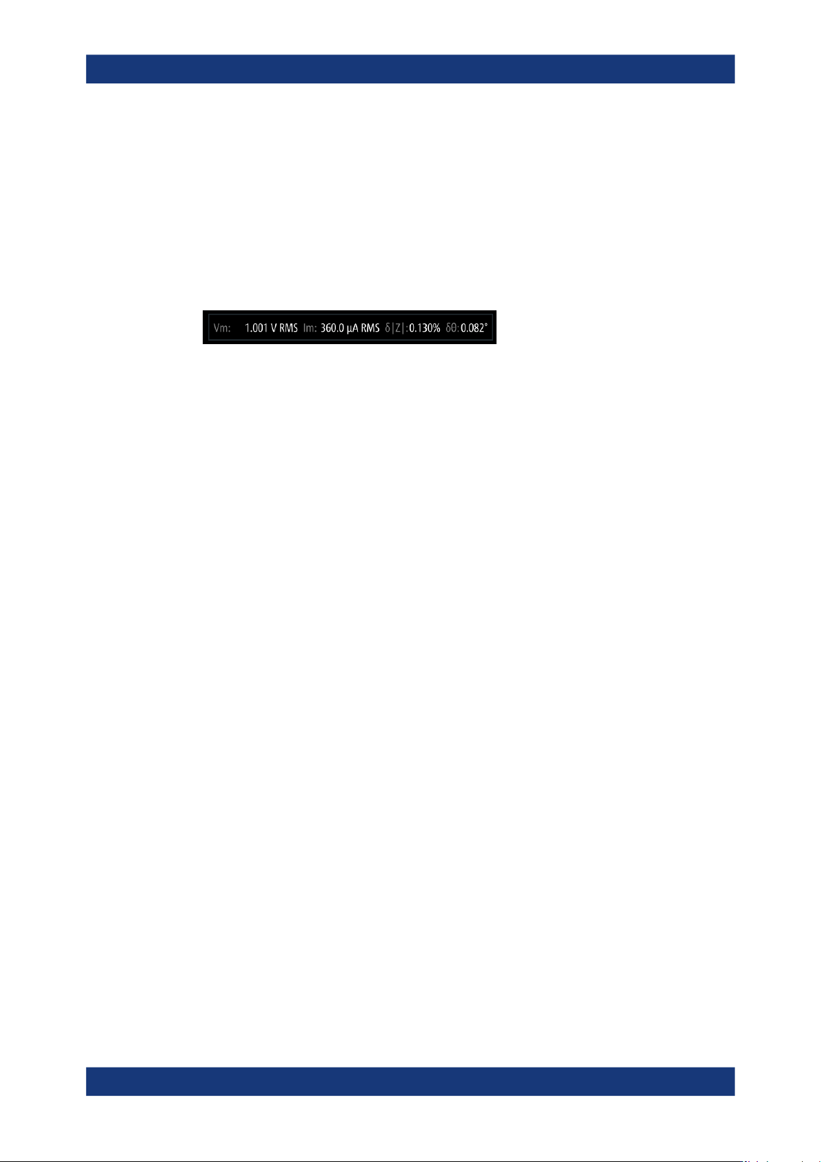
<measurement accuracy>
The test signal monitor indicates the accuracy of the recent measurement.
Remote command:
FETCh:ACCuracy? on page 206
8.2.2 Configuring the main view
Selecting the parameters
To select the measurement parameters:
1. At the front panel, press the [home] key.
2. Select the parameter pair softkey in the upper left corner of the screen, to open the
selection editor.
3. Select the corresponding measurement pair.
4. Confirm the selection.
5. Select the second measurement pair accordingly.
The R&S LCX displays the selected parameter pairs in the numeric view.
8.3 Measurement functions
The hardkeys provided in the function panel at the front select the measurement com-
ponent type.
Functions [hardkeys].....................................................................................................73
Functions [hardkeys]
Selects the type of component sample to be measured.
Remote command:
FUNCtion:MEASurement:TYPE on page 214
Measurement functions

Instrument functions
R&S
®
LCX Series
74User Manual 1179.2260.02 ─ 08
8.4 Test signal functions
In this context referred to as test signal parameters, these parameters consider all set-
tings the test signal is composed of. As the core parameters of a measurement, the
R&S LCX provides the access to these settings directly on the screen, and the settings
and function keys.
8.4.1 Test signal settings
With the "Settings" functions, you can define the main characteristics of the test signal.
Access:
1. For accessing the core parameters frequency, level, impedance range and bias,
you have the following options:
● Select the softkey of the corresponding parameter on the screen, e.g. "Fre-
quency:".
● Press the hardkey of the corresponding parameter at the front panel, e.g.,
[Freq.].
On-screen keypads open providing the corresponding entry fields for setting the
value and the unit of the selected parameter.
2. Enter the value and unit accordingly.
3.
Confirm with
.
The required remote commands are described in:
● Section 11.4, "Test signal commands", on page 185
● Section 11.11, "FUNCtion subsystem", on page 209
● Section 11.5, "BIAS subsystem", on page 188
Frequency: / [Freq.].......................................................................................................74
Level: / [Level]...............................................................................................................74
Range: / [Range]...........................................................................................................75
Current Bias: / [Bias Level]............................................................................................75
Voltage Bias: / [Bias Level]............................................................................................75
[Comp.]..........................................................................................................................75
[Bias Enable].................................................................................................................75
Frequency: / [Freq.]
Sets the test signal frequency.
Remote command:
FREQuency[:CW] on page 187
Level: / [Level]
Sets level of the AC test signal.
To select the parameter for the level setting, see "Test Signal Type" on page 80.
See "About measurement parameters" on page 76.
Test signal functions