LCX_UserManual_en_08_1.pdf - 第27页
Getting started R&S ® LCX Series 27 User Manual 1 179.2260.02 ─ 08 4.1.10 Switching on or off Switching on the product The product is off but connected to power . 1. Set the switch on the power supply to position [I]…
Getting started
R&S
®
LCX Series
26User Manual 1179.2260.02 ─ 08
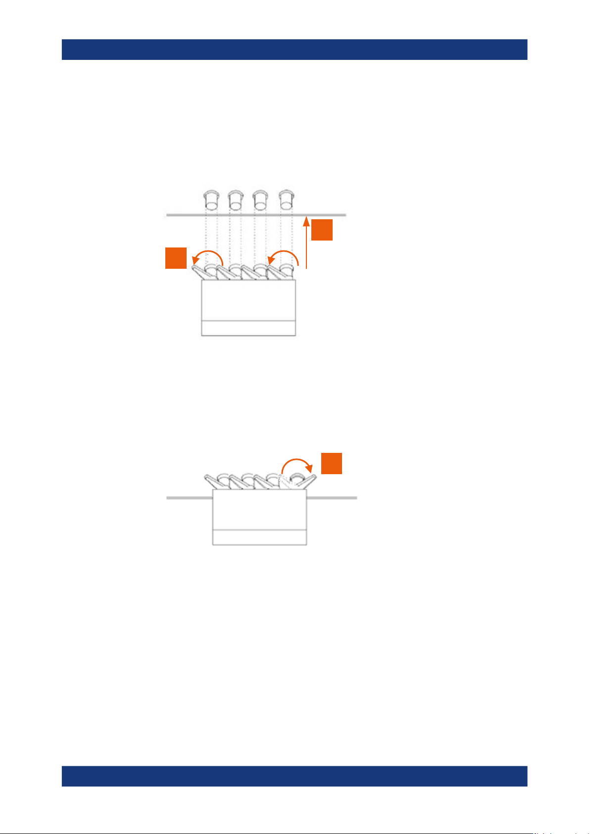
Turn the levers at the "BNC" connectors of the test fixture to the left to release the
lock (1).
1
2
Figure 4-2: Connecting a test fixture
2. Carefully plug the test fixture to the four "BNC" measurement connectors of the
R&S LCX (2).
3. Turn all levers to the right to tighten the connection (3).
3
Figure 4-3: Fastening the test fixture
The mechanical test setup is ready for operation.
Connecting a test fixture with the BNC-to-BNC extension
If you are using the BNC-to-BNC extension (option R&S LCX-Z11), you can connect all
devices as described in Connecting a test fixture to the instrument. We recommend
that you keep the order as follows:
1. Connect the BNC-to-BNC to the R&S LCX.
Proceed as described in step 1.
2. Connect the test fixture to the extension.
Preparing for use

Getting started
R&S
®
LCX Series
27User Manual 1179.2260.02 ─ 08
4.1.10 Switching on or off
Switching on the product
The product is off but connected to power.
1. Set the switch on the power supply to position [I].
The power supply switch connector is on the rear panel.
The R&S LCX starts, and the front panel keys light up briefly.
2. Press the power key for a second.
The power is on the front panel.
The instrument checks the system, boots the operating system, and then starts the
R&S LCX firmware.
The power lights green.
When starting for the first time, the R&S LCX starts with the default settings. When
restarting the instrument, the settings depend on the instrument configuration
before shut-down.
Shutting down the product
► Press the power key.
All current settings are saved and the operating system shuts down.
The power changes to gray (off).
To disconnect from power
The product is in the standby state.
1.
NOTICE! Risk of data loss. If you disconnect the product from power when it is in
the ready state, you can lose settings and data. Shut it down first.
Set the switch on the power supply to position [0].
2. Disconnect the product from the power source.
4.2 Instrument tour
The following topics help you to get familiar with the instrument and perform the first
steps:
●
Front panel tour
●
Rear panel tour
The sections explain the controls and connections at the front and back of the
R&S LCX. For specifications of the interfaces, see the specifications document.
The meanings of the labels on the R&S LCX are described in Section 1.2, "Labels on
the R&S LCX", on page 12.
Instrument tour
Getting started
R&S
®
LCX Series
28User Manual 1179.2260.02 ─ 08
4.2.1 Front panel tour
1 2 3 4 5 6
79
10
11
8
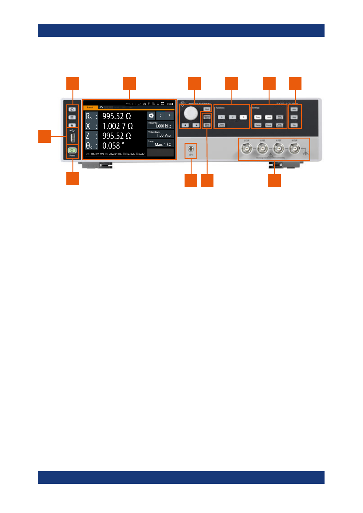
Figure 4-4: R&S
LCX front panel
1 = Basic display keys, see "Basic display keys" on page 29
2 = Touchscreen display, see Section 4.2.1.1, "Touchscreen display", on page 28
3 = Navigation controls, see "Navigation controls" on page 29
4 = Function keys, see "Function keys" on page 30
5 = Setting keys, see "Settings keys" on page 30
6 = Measurement control keys, see "Measurement control keys" on page 30
7 = BNC measurement connectors, see "L CUR, L POT, H CUR, H POT" on page 31
8 = Measurement mode keys, see "Measurement mode keys" on page 30
9 = Ground connector, see "Ground socket" on page 31
10 = POWER key, see "POWER On/Standby key" on page 31
11 = USB host connector
4.2.1.1 Touchscreen display
The color TFT touchscreen at the front panel is the graphical user interface. It shows
the measurement readings, status information and settings, and provides access to
settings dialogs.
Instrument tour