LCX_UserManual_en_08_1.pdf - 第126页
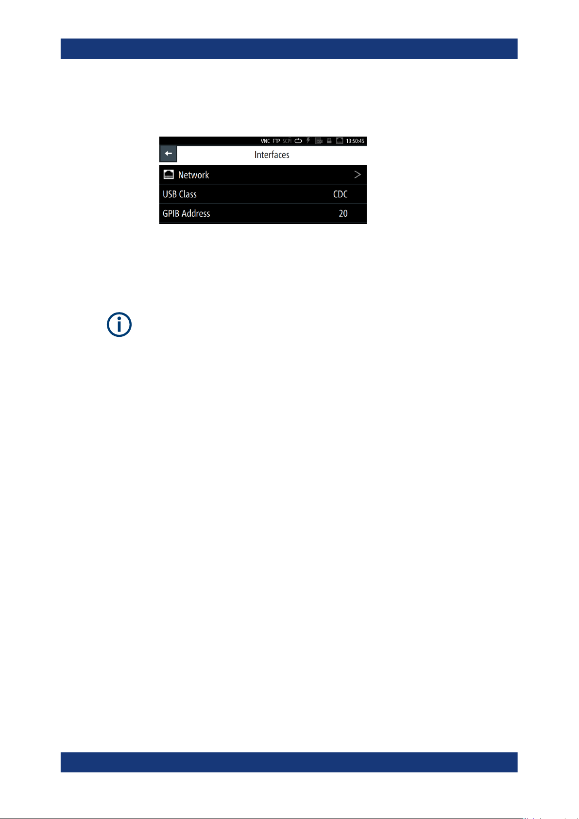
General instrument functions R&S ® LCX Series 126 User Manual 1 179.2260.02 ─ 08 2. In the "Device" tab, select "Interfaces". 3. Select the corresponding menu item. Figure 9-5: Interfaces menu In …
General instrument functions
R&S
®
LCX Series
125User Manual 1179.2260.02 ─ 08
9.1.5 Data and file types
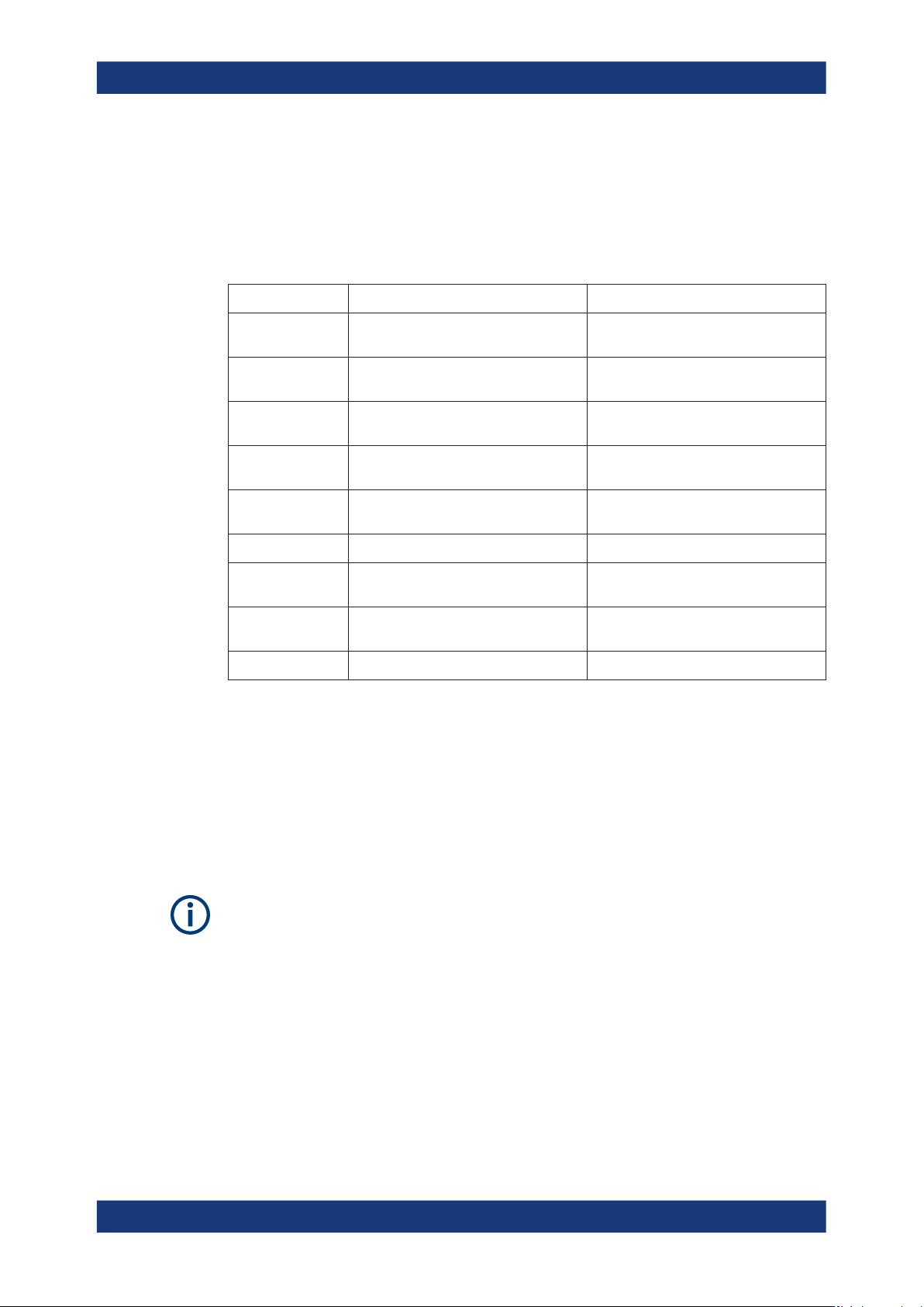
The R&S LCX distinguishes the files according to their extensions; each type of file is
assigned a specific file content and also a specific file extension. The extension is pre-
defined, e.g. you can save and load files with logging data only as *.csv files.
Table 9-1: Overview of data and file types
Data type File extension Description
Binning
*.csv
See Section 8.8.5, "Binning",
on page 110
Documentation
*.pdf
Getting Started manual, and OSA (Open
Source Acknowledgment).
Logging
*.csv
See Section 8.8.3, "Logging",
on page 101
Screenshot
*.png
See Section 9.4, "Screenshot",
on page 128
Settings
*.savrcl
See Section 9.12, "Save/recall",
on page 142
Service
*.rsd
Device information
*.rsd
See Section 9.10, "Device information",
on page 138
Firmware
*.rsu
See Section 9.11, "Update device",
on page 140
Licenses
*.xml
See Section 9.9, "Licenses", on page 135
9.2 Interfaces
The R&S LCX provides a LAN, a USB and, optionally a GPIB (IEC/IEEE) bus interface
for controlling the instrument remotely.
In the "Interfaces" menu, you can access the settings dialogs for configuring the gen-
eral network environment and specific identification parameters of the instrument.
The following description introduces the access to the interface settings. For detailed
information on connection, protocols and additional configurations, see Section 10,
"Network operation and remote control", on page 149. This section also covers the set-
ting parameter descriptions and step-by-step instructions for setting up remote control
for each interface.
9.2.1 Interface settings
Access:
1. Press the [settings] key at the front panel.
Interfaces
General instrument functions
R&S
®
LCX Series
126User Manual 1179.2260.02 ─ 08
2. In the "Device" tab, select "Interfaces".
3. Select the corresponding menu item.
Figure 9-5: Interfaces menu
In the "Interfaces" menu, you can access the settings dialogs for configuring the
general network environment and specific identification parameters of the instru-
ment.
As the settings for the dedicated interfaces relate closely to the remote control environ-
ment, see the description in Section 10.3, "Remote access settings", on page 159.
Network
Opens the "Network" connection dialog to configure the Ethernet connection.
USB Class
Opens a selection dialog to set the communication protocol for the USB interface, see
Section 10.3.5, "USB settings", on page 166.
About: see Section 10.2.2, "USB interface", on page 154.
How to: see Section 10.5, "Adjusting interface addresses", on page 169
GPIB Address
Option: R&S NG-B105 GPIB (IEC 625/IEE 488) bus interface
Opens an on-screen keypad for setting the channel address of the address GPIB bus
interface, see Section 10.3.6, "GPIB settings", on page 167.
About: see Section 10.2.3, "GPIB interface (IEC/IEEE bus interface)", on page 155
How to: see Section 10.5, "Adjusting interface addresses", on page 169.
9.2.2 Configuring interfaces
As the information on how to establish and configure a remote control connection
relates closely to the remote control environment, see:
●
Section 10.4, "Connecting the R&S LCX for remote access", on page 167
●
Section 10.5, "Adjusting interface addresses", on page 169
Interfaces
General instrument functions
R&S
®
LCX Series
127User Manual 1179.2260.02 ─ 08
9.3 User button
The user button enables you to assign a certain function to the [★ (User)] key for quick
access.
9.3.1 User button settings
Access:
1. Press the [settings] key at the front panel.
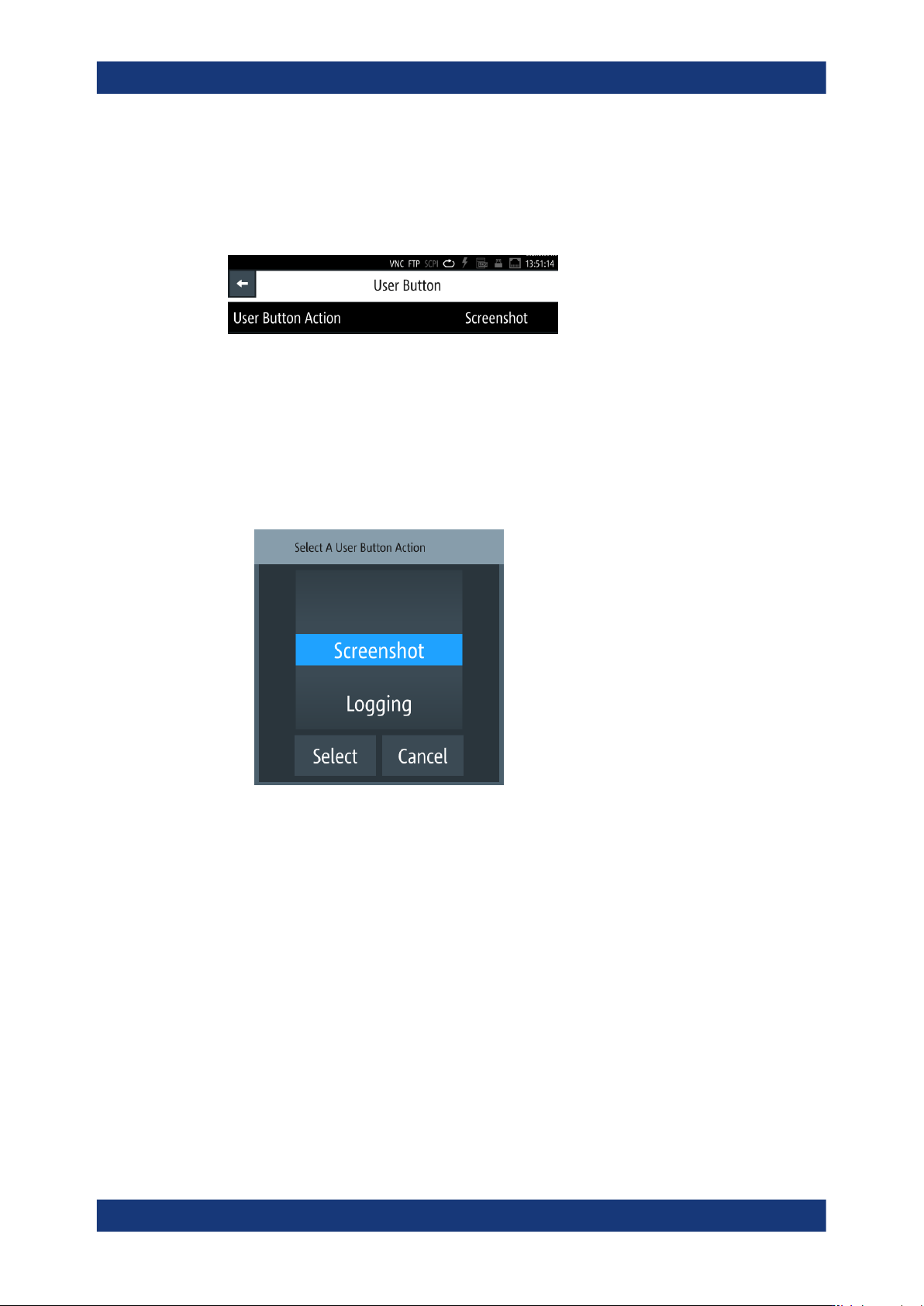
2. In the "Device" tab, select "User Button".
Figure 9-6: User button
The menu lists the functions you can assign to the [★ (User)] key:
● "Screenshot" captures an image of the screen, see Section 9.4, "Screenshot",
on page 128.
● "Logging", see Section 8.8.3, "Logging", on page 101.
● "Touch Lock" locks and unlocks the touchscreen operation (toggle function).
How to: see "Assigning the touch lock function to the "User Button""
on page 128
● "Open Correction" starts calibration on all frequencies for open test fixtures
contacts.
How to: see Section 6.2, "Configuring the test signal", on page 59
● "Short Correction" starts calibration on all frequencies for short-circuit test fix-
tures contacts.
How to: see Section 6.2, "Configuring the test signal", on page 59
● "Open/Short Correction" starts calibration on all frequencies for open/short-cir-
cuit test fixtures contacts.
User button