LCX_UserManual_en_08_1.pdf - 第87页
Instrument functions R&S ® LCX Series 87 User Manual 1 179.2260.02 ─ 08 3. Y ou have connected the test fixture, see Section 4.1.9, "Connecting a test fixture" , on page 25. Tip: For information on how to h…
Instrument functions
R&S
®
LCX Series
86User Manual 1179.2260.02 ─ 08
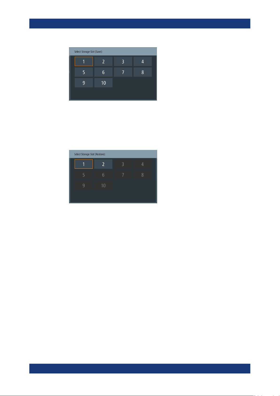
Figure 8-8: Correction storage save editor
Remote command:
CORRection:STORage:SAVE on page 196
Restore Corrections
Opens an on-screen editor for selecting a memory slot for restoring correction data.
Figure 8-9: Correction storage restore editor
Remote command:
CORRection:STORage:RESTore on page 196
8.6.3 Performing open/short/load correction
The following procedures provide a brief overview of the steps required to perform the
corrections. They point out special features, such as load correction.
See also "Open/Short/Load correction", "Spot correction" and "Save/Restore correction
data" under "About measurement parameters" on page 76.
Previous steps
We assume that you have prepared the measurement as follows:
1. You have set up and turned on the R&S LCX, see Section 4.1, "Preparing for use",
on page 18.
2. You have set the R&S LCX to an initial state, see "Setting the initial state"
on page 34.
Measurement parameters
Instrument functions
R&S
®
LCX Series
87User Manual 1179.2260.02 ─ 08
3. You have connected the test fixture, see Section 4.1.9, "Connecting a test fixture",
on page 25.
Tip: For information on how to handle the connection pins of the individual test fix-
tures during correction, see Section 6.1, "About test fixtures", on page 53.
Aligning the instrument on all frequencies
To perform a full correction:
1. Set up the test signal, see "Setting up the test signal" on page 35.
2. If you are using the BNC-to-BNC extension (option R&S LCX-Z11), consider the
cable length:
a) Press the [settings] key at the front panel.
b) Select the "Measurement" tab.
c) Set "Cable Length" to "1 m".
3. Set the "Source Impedance" as required for your measurement, set e.g. "High Z
100".
4. Select "Open/Short/Load Correction".
5. To perform the open and short correction, proceed as described in "Aligning the
instrument on all frequencies" on page 36.
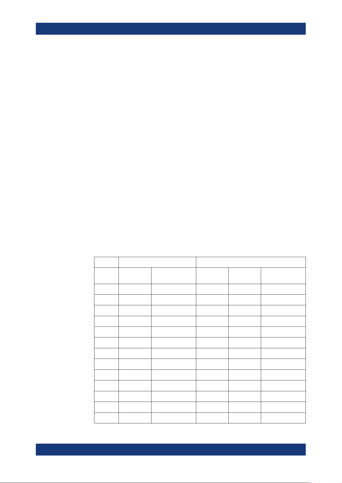
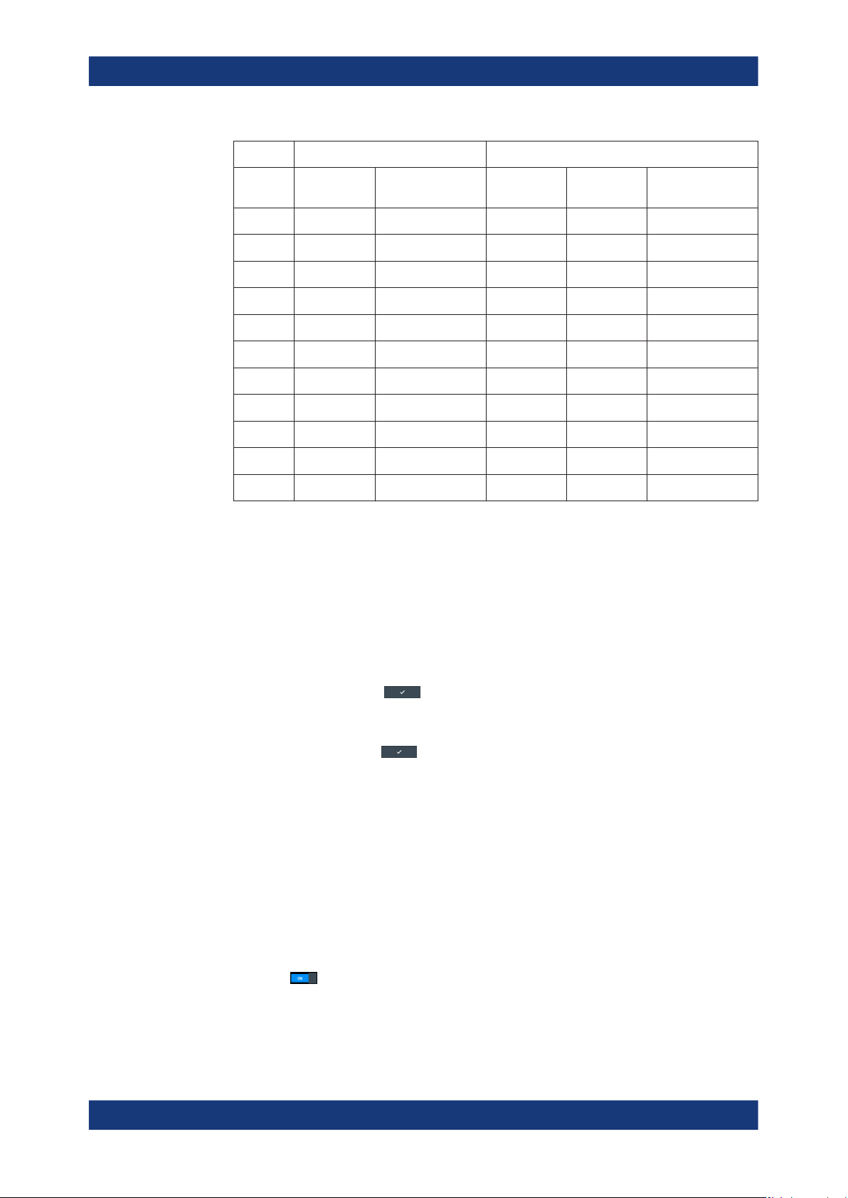
During full correction, i.e. alignment on all frequencies, the R&S LCX performs the
correction on the following frequencies, according to the set source impedance and
correction mode:
Table 8-1: Frequency sequences for open and short correction
Open correction Short correction
Fre-
quency
High Z 100 Ω High Voltage > 2V Low Z 10 Ω High Z 100 Ω High Voltage > 2V
DC -- -- x x x
4 Hz x x x x x
8 Hz x x x x x
16 Hz x x x x x
100 Hz x x x x x
1 kHz x x x x x
10 kHz x x x x x
30 kHz x x x x x
50 kHz x x x x x
100 kHz x x x x x
150 kHz x x x x x
200 kHz x x x x x
300 kHz x x x x x
Measurement parameters
Instrument functions
R&S
®
LCX Series
88User Manual 1179.2260.02 ─ 08
Open correction Short correction
Fre-
quency
High Z 100 Ω High Voltage > 2V Low Z 10 Ω High Z 100 Ω High Voltage > 2V
500 kHz x x x x x
1 MHz x x x x x
2 MHz x
x
3 MHz x
x
4 MHz x
x
5 MHz x
x
6 MHz x
x
7 MHz x
x
8 MHz x
x
9 MHz x
x
10 MHz x
x
The corresponding icon in the measurement status bar turns white, indicating that
compensation is active, see "Measurement status bar" on page 41.
Aligning the instrument on a dedicated working point
To perform a spot correction:
1. To set the working point:
a) Press the [Freq.] key at the front.
b) Enter the test signal frequency, e.g. 10 kHz using the keypad on the screen.
c)
Confirm you setting
.
d) Press the [Level] key.
e) Enter the level, e.g. 1.3 VRMS.
f)
Confirm the setting
.
g) Press the [Range] key.
Note: To achieve most accuracy, we recommend that you perform all spot cor-
rections in the "Auto" measurement range.
h) In the measurement range dialog, select "Auto".
2. Press the [Comp.] key at the front panel.
The "Open/Short/Load Correction" dialog opens.
3. Perform an open spot correction, in this example described for the axial/radial lead
type test fixture (R&S LCX-Z1):
a) Select "Open Correction".
b)
Turn
"Enabled".
Measurement parameters