LCX_UserManual_en_08_1.pdf - 第82页
Instrument functions R&S ® LCX Series 82 User Manual 1 179.2260.02 ─ 08 Based on the set purity angle referred to as A, and the measured angle M, the auto function assumes the following components: Angle Component -A…

Instrument functions
R&S
®
LCX Series
81User Manual 1179.2260.02 ─ 08
Measurement Mode
Enables or disables the continuous measurement mode.
The R&S LCX starts a measurement cycle initiated by a trigger signal.
"Cont."
Measures continuously, i.e. starts with the next measurement cycle
after a measurement has been completed.
"Trig."
Performs one measurement cycle. After a measurement has been
completed, the R&S LCX stops and waits for the next trigger signal.
Remote command:
TRIGger:CONTinuous on page 242
TRIGger[:IMMediate] on page 243
*TRG on page 185
Trigger Delay
Sets the delay between the trigger event and the actual start of the measurement.
You can increase or decrease the delay in steps of 1 ms increment.
Remote command:
TRIGger:DELay on page 242
Voltage Bias
Selects voltage bias to be used.
To set the value, see Section 6.3.2, "External voltage bias", on page 62.
"Int."
Enables the internal voltage bias.
"Ext."
Requires option: R&S LCX-K108
Uses an external voltage bias, if supplied.
Note: Make sure that the external DC voltage source supplies a con-
stant voltage bias to avoid distortion of the measurement results due
to interference.
Remote command:
BIAS:STATe on page 189
Open/Short/Load Correction
Opens the dialog for activating the correction functions, see Section 8.6.2, "Open/short/
load correction settings", on page 82.
Auto Function
Opens the dialog for configuring the auto function parameters.
During the measurement, the auto function refers to the purity angle that is set in the
instrument, and the measured value. Concerning the separation point, the function
determines the equivalent circuit based on the estimated absolute value of Z.
See also:
●
About measurement parameters > Auto function
●
Measurement basics > Figure 5-1
Purity Angle ← Auto Function
Sets the switching point of the phase angle.
Measurement parameters
Instrument functions
R&S
®
LCX Series
82User Manual 1179.2260.02 ─ 08
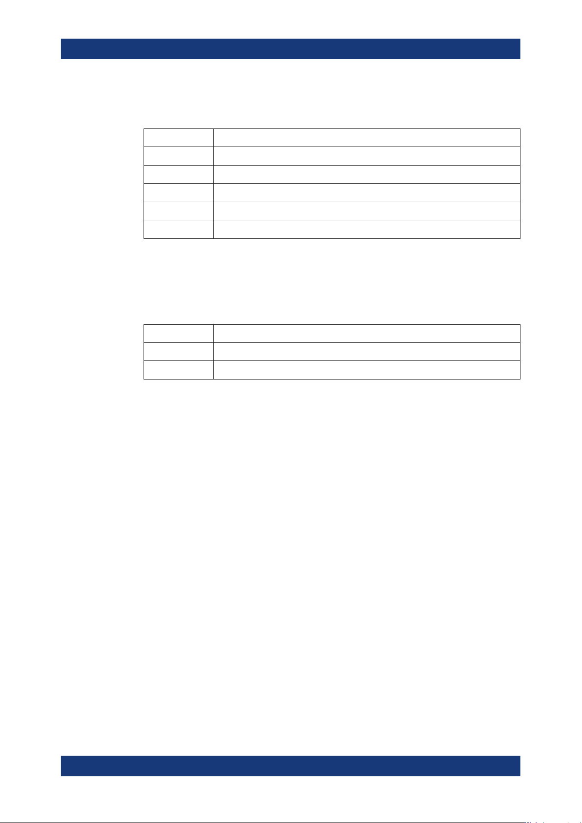
Based on the set purity angle referred to as A, and the measured angle M, the auto
function assumes the following components:
Angle Component
-A ≤ M ≤ A pure resistance
90°-A ≤ M ≤ 90° pure inductance
A-90° ≤ M ≤ -90° pure capacitance
A < M < 90° resistance and inductance
-A < M < -90° resistance and capacitance
Serial/Parallel Separation Point ← Auto Function
Sets the threshold for the function to switch from serial to parallel impedance measure-
ment, according to the equivalent circuit.
Based on the set separation point S, and the measured impedance Z, the auto function
assumes the following equivalent circuits:
Impedance Equivalent circuit
0 ≤ Z ≤ S serial measurement
S < Z < range parallel measurement
8.6.2 Open/short/load correction settings
The correction dialog enables you to use the correction techniques provided by the
instrument.
Depending on the connected test fixture and the type of component sample to be mea-
sured, refer to the description on how to perform the corresponding corrections, see
Section 6.1, "About test fixtures", on page 53.
Access:
1. Press the [settings] key at the front panel.
2. Select the "Measurement" tab.
Measurement parameters
Instrument functions
R&S
®
LCX Series
83User Manual 1179.2260.02 ─ 08
3. Select "Open/Short/Load Correction".
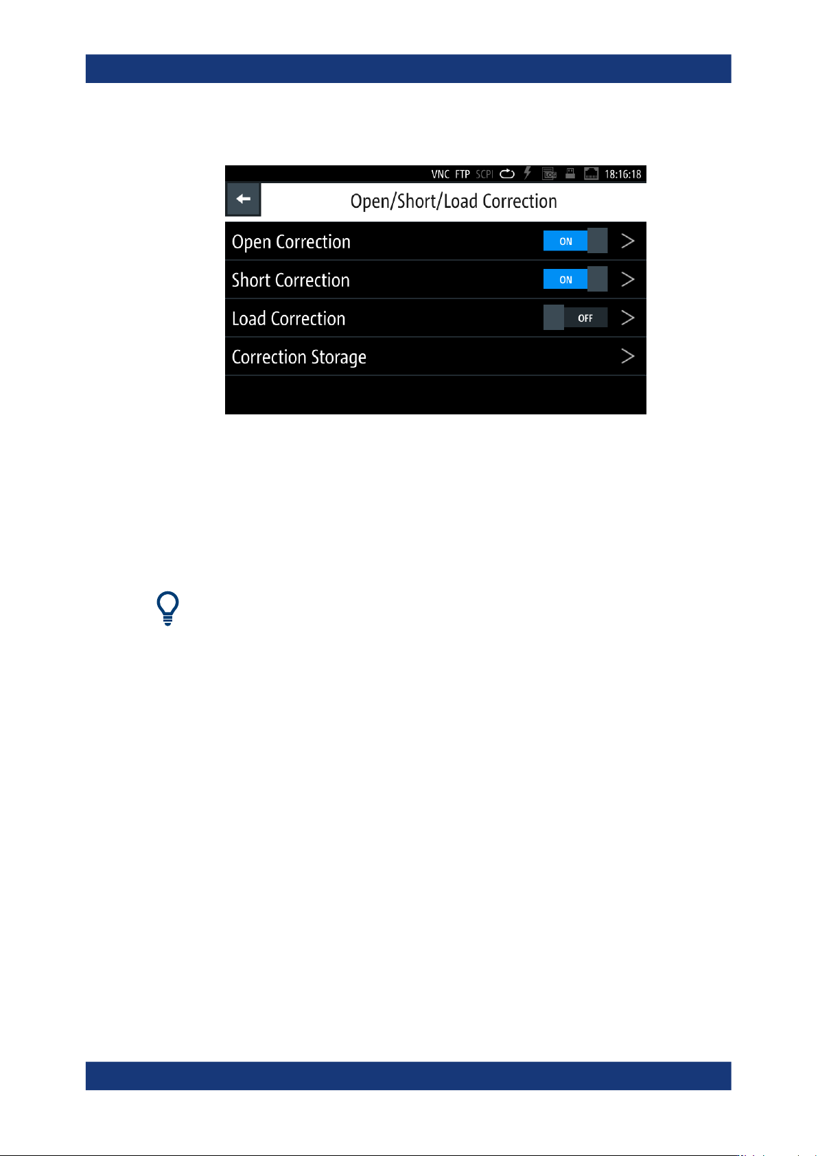
Figure 8-3: Open/Short/Load correction dialog
In this menu, you can enable the corresponding corrections directly, and access
the subdialogs to configure and start the corrections. You can save the correction
data of "Open/Short (FULL)" for later reuse.
The required remote commands are described in: Section 11.6, "CORRection sub-
system", on page 190
How to: see Section 8.6.3, "Performing open/short/load correction", on page 86.
If you need to perform the open and short correction frequently, you can assign these
functions to the [★ (User)] key and perform them with just one keystroke, see Sec-
tion 9.3, "User button", on page 127.
Settings
Open/Short/Load Correction Enabled...........................................................................83
Start Short/Open Correction (Spot)...............................................................................84
Start Short/Open Correction (Full)................................................................................ 84
Start Load Correction (Spot)......................................................................................... 85
Reference Load R.........................................................................................................85
Reference Load X......................................................................................................... 85
Correction storage.........................................................................................................85
Save Corrections...........................................................................................................85
Restore Corrections...................................................................................................... 86
Open/Short/Load Correction Enabled
Enables the corresponding correction function.
To start a correction process, select the corresponding Start Short/Open Correction
(Full) or Start Short/Open Correction (Spot) entry of the respective correction.
Measurement parameters