LCX_UserManual_en_08_1.pdf - 第58页
Measurement setups R&S ® LCX Series 58 User Manual 1 179.2260.02 ─ 08 Figure 6-5: R&S LCX-Z5 transformer test fixture and test cables The test fixture comes with four test leads equipped with alligator clips, to …
Measurement setups
R&S
®
LCX Series
57User Manual 1179.2260.02 ─ 08
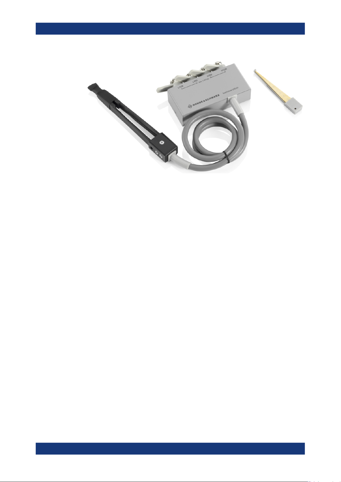
Figure 6-4: R&S
LCX-Z4 SMD test tweezers
The test fixture is equipped with tweezers, and miniature SMD tweezers.
To perform a short correction, hold the contacts of the tweezers closed. For open cor-
rection, leave the contacts open.
6.1.5 Test fixture with cables for transformer components
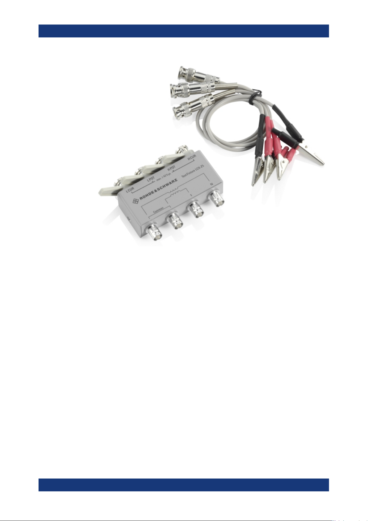
The transformer R&S LCX-Z5 test fixture is designed for measuring transformers or
transmitters in combination with transformers.
About test fixtures
Measurement setups
R&S
®
LCX Series
58User Manual 1179.2260.02 ─ 08
Figure 6-5: R&S
LCX-Z5 transformer test fixture and test cables
The test fixture comes with four test leads equipped with alligator clips, to contact the
primary and secondary circuits of the measurement sample. The BNC connectors on
the right and left outside are intended to contact the circuit with the higher number of
windings. The two BNC connectors in the middle are intended for the circuit with lower
number of windings.
As an alternative, it is possible to install a user-specific test setup at the BNC connec-
tors directly.
6.1.6 BNC-to-BNC extension
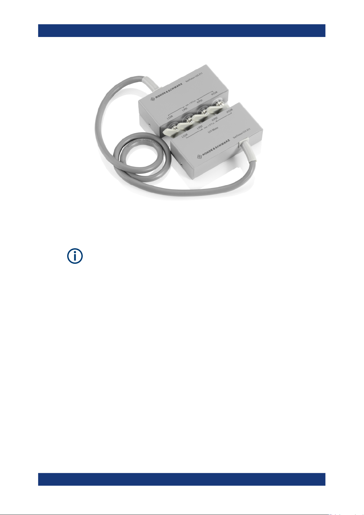
The R&S LCX-Z11 BNC-to-BNC extension (1m) enables you to place the test setup in
the distance of 1 m from the site of the R&S LCX.
About test fixtures
Measurement setups
R&S
®
LCX Series
59User Manual 1179.2260.02 ─ 08
Figure 6-6: R&S
LCX-Z11 BNC-to-BNC extension
The extension also provides four BNC measurement ports for connecting a test fixture
or establish user-specific connection.
When you use the R&S LCX-Z11 BNC-to-BNC extension, you must set the cable
length to 1 m in the measurement settings for cable length compensation, see Sec-
tion 8.6.1, "Measurement parameter settings", on page 78.
How to: see "Connecting a test fixture with the BNC-to-BNC extension" on page 26
6.2 Configuring the test signal
The accuracy of the measured impedance depends mainly on the test frequency and
level. Therefore, each measurement requires that you specify the test signal to obtain
results under defined conditions.
In addition to the frequency and level settings, e.g. to measure at a certain working
point, you can define a measurement range. E.g., if you want to analyze the behavior
of a component over a certain range. For measurements of coils or capacitors you can
superimpose a current, or voltage bias, respectively.
We assume that you have set up the R&S LCX as described in Section 4.1.4, "Setting
up the R&S LCX", on page 19. For basic information on setting up a measurement,
including the test signal, see the example in "Basic measurement steps" on page 34.
For details on the setting parameters, see Section 8, "Instrument functions",
on page 70.
The following sections provide additional information to be considered for the specific
measurements.
Configuring the test signal