LCX_UserManual_en_08_1.pdf - 第68页
Performing measurements R&S ® LCX Series 68 User Manual 1 179.2260.02 ─ 08 b) Connect both, the "N" and the "Common" test leads to the secondary circuit of the transformer . Observe the polarity o…
Performing measurements
R&S
®
LCX Series
67User Manual 1179.2260.02 ─ 08
4. To measure the parameters of a transformer coil:
open
secondaryprimary
Figure 7-1: Primary inductance measurement
a) Connect the "Common" test leads of the corresponding circuit to one terminal
of the transformer winding to be measured.
b) Connect both, the "1" and the "N" test leads to the other terminal of the winding
to be measured.
c) Leave the second winding of the transformer open.
To measure the secondary inductance of the transformer, connect the secondary
winding to the R&S LCX-Z5 and leave the primary winding open.
Measuring the transformer ratio and the mutual inductance of a transformer
This example refers to a measurement of a transformer with the test fixture (R&S LCX-
Z5).
To measure the mutual inductance, both windings are connected to the test fixture.
1. Press the [Transformer] key.
2. Set the measurement frequency, e.g. the mains frequency for a mains transformer.
3. Select the parameters for measurement results display:
a) Select the measurement pair softkey in the upper left corner, to open the selec-
tion editor.
b) Select the parameters "N-ΘNd" (transformer ratio, phase angle).
c) Repeat the steps to select the second parameters, e.g. select "M-ΘNd" (induc-
tance, phase angle).
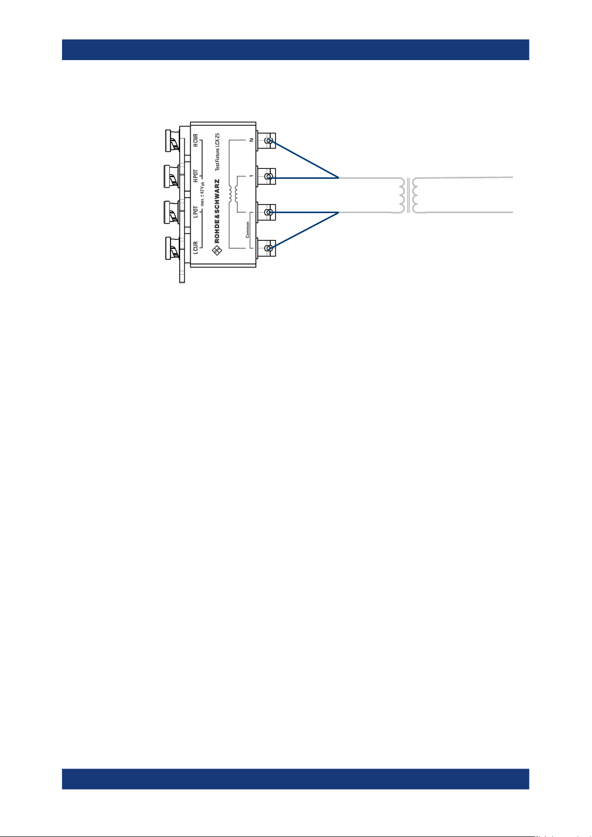
4. To measure the parameters of a transformer circuit:
a) Connect both, the "1" and the "Common" test leads of the test fixture to the pri-
mary winding of the transformer.
Performing measurements
R&S
®
LCX Series
68User Manual 1179.2260.02 ─ 08
b) Connect both, the "N" and the "Common" test leads to the secondary circuit of
the transformer. Observe the polarity of the windings, if known. Both "Common"
test leads are equivalent.
The measurement starts and you can see the readings on the screen.
The transformer ratio "N-ΘNd" is the ratio between measured primary voltage and
measured secondary voltage.
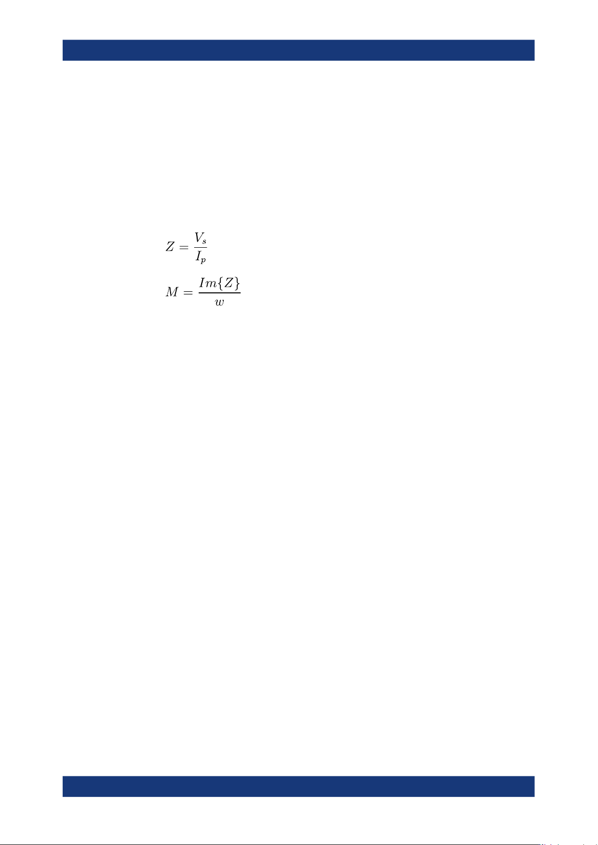
The mutual inductance "M-ΘNd" is calculated from measured primary current "I
p
"
and the measured secondary voltage "V
s
" as follows (Z is a virtual complex impe-
dance value):
Z
= virtual impedance
V
s
= measured voltage in secondary circuit
I
p
= measured current in primary circuit
M = mutual inductance
Im{Z} = imaginary part of impedance
ω
= angular frequency
If ΘNd is between 90° and 270°, the transformer inverts the signal. In this case, the
"M" result can display "RANGE" instead of a value. Invert the connection of one of
the windings to obtain a non-inverting setup and a valid measurement result
for "M".
Measuring the leakage inductance of a transformer
This example refers to a measurement of a transformer with the test fixture (R&S LCX-
Z5). You can also use only the included standard cables for inductance measurements
without the test adapter.
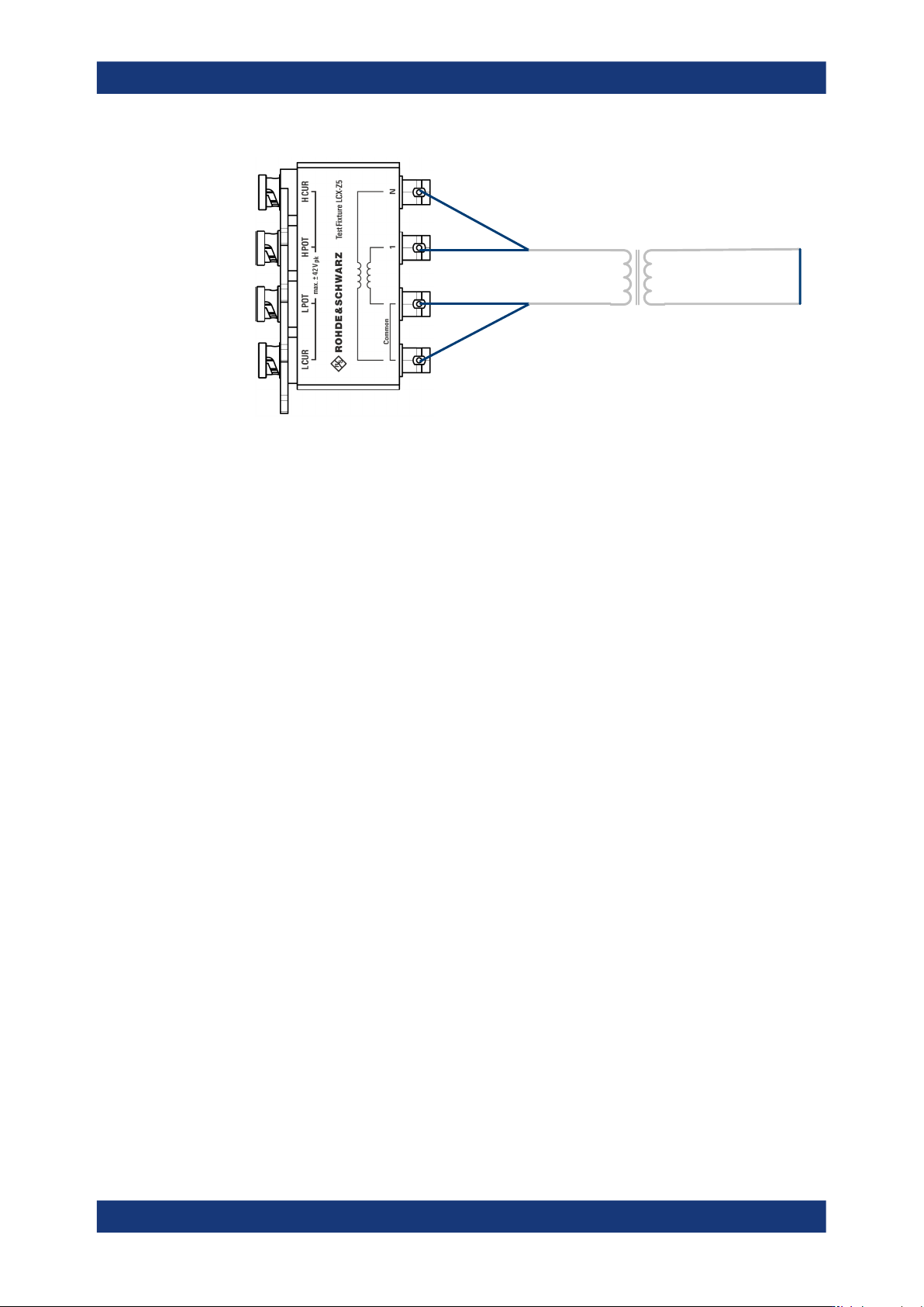
The connections and measurement settings are the same as for primary inductance
measurement, except that the secondary winding is shorted.
1. To select the inductance measurement (DUT component type), press the [L] key.
2. Set the measurement frequency, e.g. the mains frequency for a mains transformer.
3. Select the parameters for measurement results display as described under "Mea-
suring an inductor" on page 66.
4. Short-circuit the secondary winding of the transformer.
Performing measurements
R&S
®
LCX Series
69User Manual 1179.2260.02 ─ 08
short
secondaryprimary
Figure 7-2: Leakage inductance measurement
The inductance value of the primary winding measured with secondary winding
shorted corresponds to the primary leakage inductance.
To measure the secondary leakage inductance, connect the secondary winding
instead of the primary to the R&S LCX-Z5 and short circuit the primary winding.