LCX_UserManual_en_08_1.pdf - 第42页
Getting started R&S ® LCX Series 42 User Manual 1 179.2260.02 ─ 08 Indicator Description "BIAS" Indicates an activated bias: ● "VBIAS": voltage bias, provided for capacitance measurements ● "…
Getting started
R&S
®
LCX Series
41User Manual 1179.2260.02 ─ 08
Indicator Description
GPIB/IEE-488 The IEE-488 bus interface (GPIB) connection is established.
See Section 10.4, "Connecting the R&S LCX for remote access",
on page 167.
Time
Indicates the time set on the instrument.
See Section 9.6, "Date & time", on page 132.
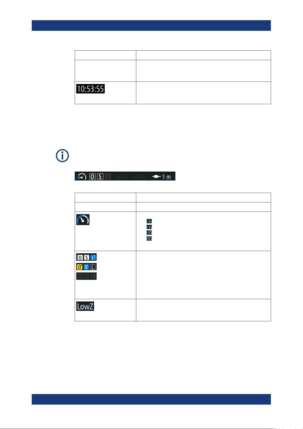
Measurement status bar
The measurement status bar provides information on certain measurement modes,
functions and states. When activated, indicators displayed in white color represent the
corresponding functions.
For information on the measurement modes and functions, see "About measurement
parameters" on page 76.
Table 4-8: Measurement status bar
Indicator Description
Measurement mode
Measurement speed
Indicates the set measurement speed:
●
superfast, 4 ms
●
fast, 15 ms
●
medium, 100 ms
●
slow, 500 ms
See "Speed" on page 80
"O", "S", "L"
Indicates the state of open, short, and load correction.
●
white: full correction enabled
●
blue: spot correction enabled
●
yellow: questionable spot correction
●
black: uncorrected
●
gray: correction disabled
The dot "˙" at the top right indicates spot correction.
See Section 8.6.2, "Open/short/load correction settings", on page 82
"LowZ"
The low impedance measurement mode is set.
See "Source Impedance" on page 80
Instrument control
Getting started
R&S
®
LCX Series
42User Manual 1179.2260.02 ─ 08
Indicator Description
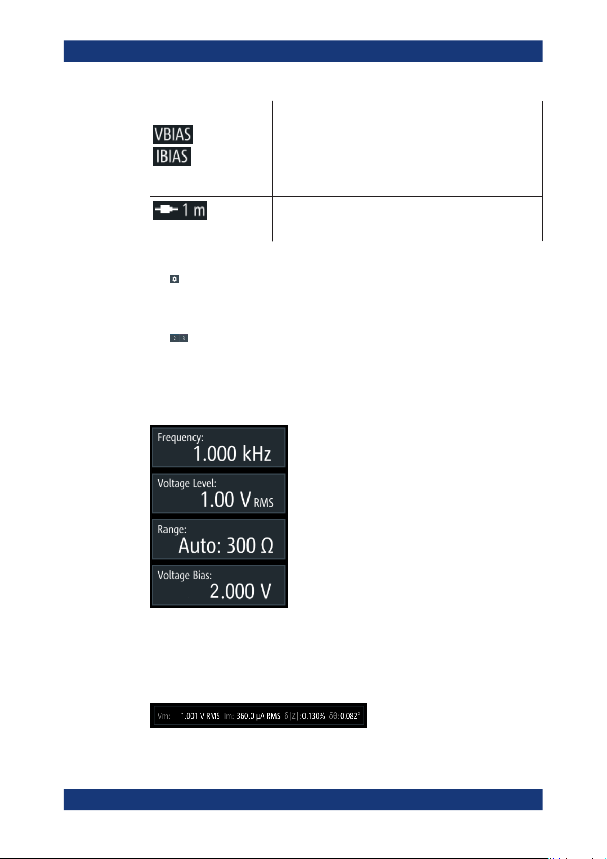
"BIAS"
Indicates an activated bias:
●
"VBIAS": voltage bias, provided for capacitance measurements
●
"IBIAS": current bias, provided for inductance measurements
●
"eVBIAS": external voltage bias, for capacitance measurements
If disabled, the icons are grayed out.
See Section 8.4.1, "Test signal settings", on page 74
"Cable Length"
White indicates that the cable length is set. The R&S LCX displays the
set value (currently only 1 m applicable).
See "Cable Length" on page 80
Settings softkey
The (settings) softkey opens the measurement dialog for setting additional basic
measurement parameters.
Configuration preset softkeys
The (preset configuration) softkeys recall previously assigned measurement con-
figurations, defined for dedicated measurements. You can assign up to three predefina-
ble configuration presets.
How to: see Section 8.7.2, "Using the configuration preset function", on page 92
Signal parameters
Figure 4-8: Measurement signal parameters
Each softkey opens an on-screen keypad for setting the signal parameters directly.
Alternatively, you can use the corresponding settings keys at the front panel.
Test signal monitor
Figure 4-9: Test signal monitor of L,C, R measurements
Instrument control
Getting started
R&S
®
LCX Series
43User Manual 1179.2260.02 ─ 08
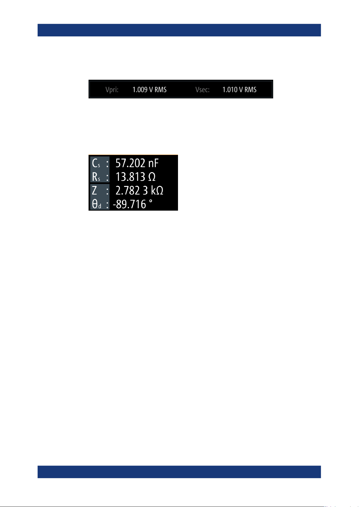
The test signal monitor displays voltage and current results and the measurement
accuracy.
Figure 4-10: Test signal monitor of transformer measurements
For transformer measurements, the test signal monitor displays the transformer induc-
tance of the primary "Vpri" and secondary "Vsec" winding.
Measurement parameters and results
Figure 4-11: Measurement results window
The initial screen shows the basic parameters capacitance "C
s
" and serial resistance
"R
s
", the impedance "Z" and phase angle "Θ
d
". On the right, the R&S LCX displays the
measurement readings.
You can select parameters different from default by tapping the parameter softkeys.
How to: see "Measuring a resistor" on page 36
The parameter softkeys open an on-screen selection list for selecting parameters other
than displayed.
Additional display characteristics
The following section provides a short insight on the indication of the screen in general,
and significant elements that you see under specific modes, in dialogs or settings.
●
Appearance of active elements
– Active elements like On/Off switches, state buttons have a blue background.
– Selected elements are framed or highlighted orange.
– Inactive elements are gray.
●
Menus and dialogs
Both menus and dialogs appear similar, and contain selection lists.
Throughout this manual, a list of functions that lead you to the settings of this func-
tion is referred to as menu. The term dialog refers to the views that cover the
parameters of a certain function. Some dialogs are divided into tabs with logically
grouped parameters.
Instrument control