LCX_UserManual_en_08_1.pdf - 第79页
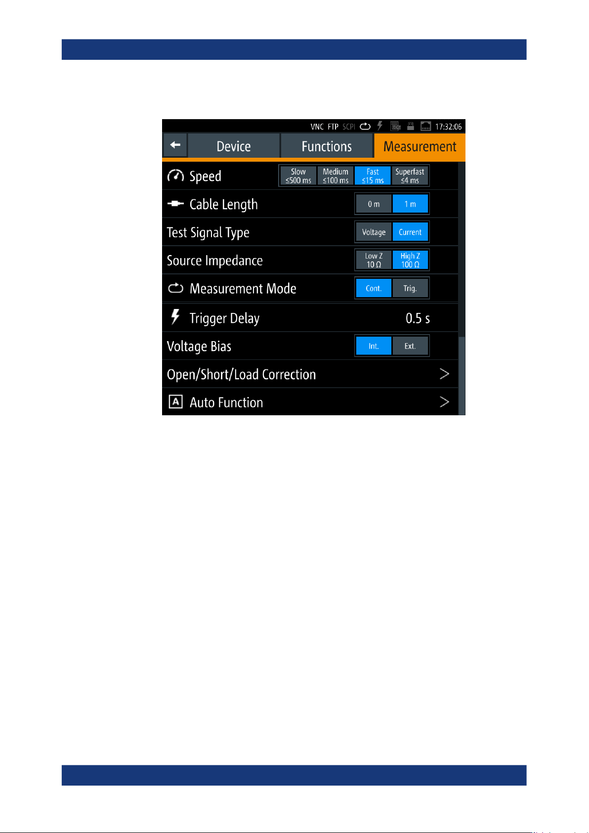
Instrument functions R&S ® LCX Series 79 User Manual 1 179.2260.02 ─ 08 2. Select the "Measurement" tab. Figure 8-2: Measurement settings dialog The dialog enables you to configure measurement conditions, e…

Instrument functions
R&S
®
LCX Series
78User Manual 1179.2260.02 ─ 08
In certain applications, you can apply the adjustment data of a spot correction to a
measurement with different settings. In this case, the R&S LCX displays the state
in different colors, see "Measurement status bar" on page 41.
Spot correction data is not applied, when you change the frequency, the cable
length, low Z/high Z or the voltage between ≤2 V and >2 V. The correction data of
the last spot correction remains persistent until a new adjustment is performed.
However, they are reset by default settings (reset), factory reset, or an instrument
restart.
●
Save/Restore correction data
The instrument provides internal memory slots to store and retrieve up to 10 cor-
rection data sets. You can save the data of all fully performed corrections (open/
short), i.e. spot and load correction data are excluded. The correction data remains
in the internal memory permanently. You can overwrite it by saving a new correc-
tion data set. A factory preset deletes the memory slots. However, correction data
sets of full corrections that are not saved explicitly remain persistent and are
restored with an instrument restart.
●
Auto function
The R&S LCX determines the component type of the DUT automatically, based on
the measured impedance and phase angle. The auto function allows you to set the
threshold values for the phase angle and the serial or parallel separation point.
The measurement principle distinguishes between pure and mixed measurement
pairs, i.e. measurement pairs with only real values (Rs-X,...), and measurement
pairs with additional imaginary components (LS-R).
Figure 5-1 under Measurement basics illustrates the relations.
See "Auto Function" on page 81.
8.6.1 Measurement parameter settings
The "Measurement" parameters define additional settings that relate, e.g., to the mea-
surement conditions.
Access:
1. Press the [settings] key at the front panel.
Measurement parameters
Instrument functions
R&S
®
LCX Series
79User Manual 1179.2260.02 ─ 08
2. Select the "Measurement" tab.
Figure 8-2: Measurement settings dialog
The dialog enables you to configure measurement conditions, e.g. cable length
from the connected test fixture, external bias of impedance measurement range.
The required remote commands are described in:
● Section 11.5, "BIAS subsystem", on page 188
● Section 11.6, "CORRection subsystem", on page 190
● Section 11.11, "FUNCtion subsystem", on page 209
● Section 11.19, "TRIGger subsystem", on page 241
How to: see Section 8.6, "Measurement parameters", on page 76
Speed............................................................................................................................80
Cable Length.................................................................................................................80
Test Signal Type............................................................................................................80
Source Impedance........................................................................................................80
Measurement Mode...................................................................................................... 81
Trigger Delay.................................................................................................................81
Voltage Bias.................................................................................................................. 81
Open/Short/Load Correction......................................................................................... 81
Auto Function................................................................................................................81
└ Purity Angle.....................................................................................................81
└ Serial/Parallel Separation Point...................................................................... 82
Measurement parameters

Instrument functions
R&S
®
LCX Series
80User Manual 1179.2260.02 ─ 08
Speed
Selects the speed of the measurement repetitions per second.
Note: The values below relate to test signal frequencies ≥1 kHz.
See also "About measurement parameters" on page 76 and the specifications docu-
ment, section "Measurment Accuracy".
"Superfast: ≤4 ms"
Number of measurements: ≈250 / s.
"Fast: ≤15 ms"
Number of measurements: ≈66 / s.
"Medium: ≤100 ms"
Number of measurements: ≈10 / s.
"Slow: ≤500 ms"
Number of measurements: ≈2 / s.
Remote command:
APERture on page 186
Cable Length
Selects the length of the leads to the connected test fixture, i.e. to the DUT.
"1 m"
Considers the cable losses of the leads from the test fixture to the
R&S LCX.
Required for the BNC-to-BNC extension (option R&S LCX-Z11), and
for test adapters with leads to the DUT. E.g., if you use other adapters
than the test adapters provided by Rohde & Schwarz.
"0 m"
The instrument does not consider cable losses.
Use this setting for test adapters that are directly connected to the
R&S LCX, i.e. the test fixtures R&S LCX-Z1/-Z2/-Z3/-Z4/-Z5.
Remote command:
CORRection:LENGth on page 192
Test Signal Type
Selects the parameter for the setting the test signal.
The setting parameter for the test signal level on the measurement window varies
according to the selection, see "Level: / [Level]" on page 74.
"Voltage"
Selects the signal level.
"Current"
Selects the signal current.
Source Impedance
Selects the output impedance for the measurement.
"Low Z 10
Ω"
Measures with 10 Ω output impedance.
"High Z 100 Ω"
(default)
Measures with 100 Ω output impedance.
Remote command:
FUNCtion:IMPedance:SOURce on page 212
Measurement parameters