LCX_UserManual_en_08_1.pdf - 第112页
Instrument functions R&S ® LCX Series 1 12 User Manual 1 179.2260.02 ─ 08 Contents of the *.csv file: ● Up to 2 measurement parameters ● The measured value range of each of the two parameters for the individual bin. …
Instrument functions
R&S
®
LCX Series
111User Manual 1179.2260.02 ─ 08
9
4
6
10
21 3
5
78
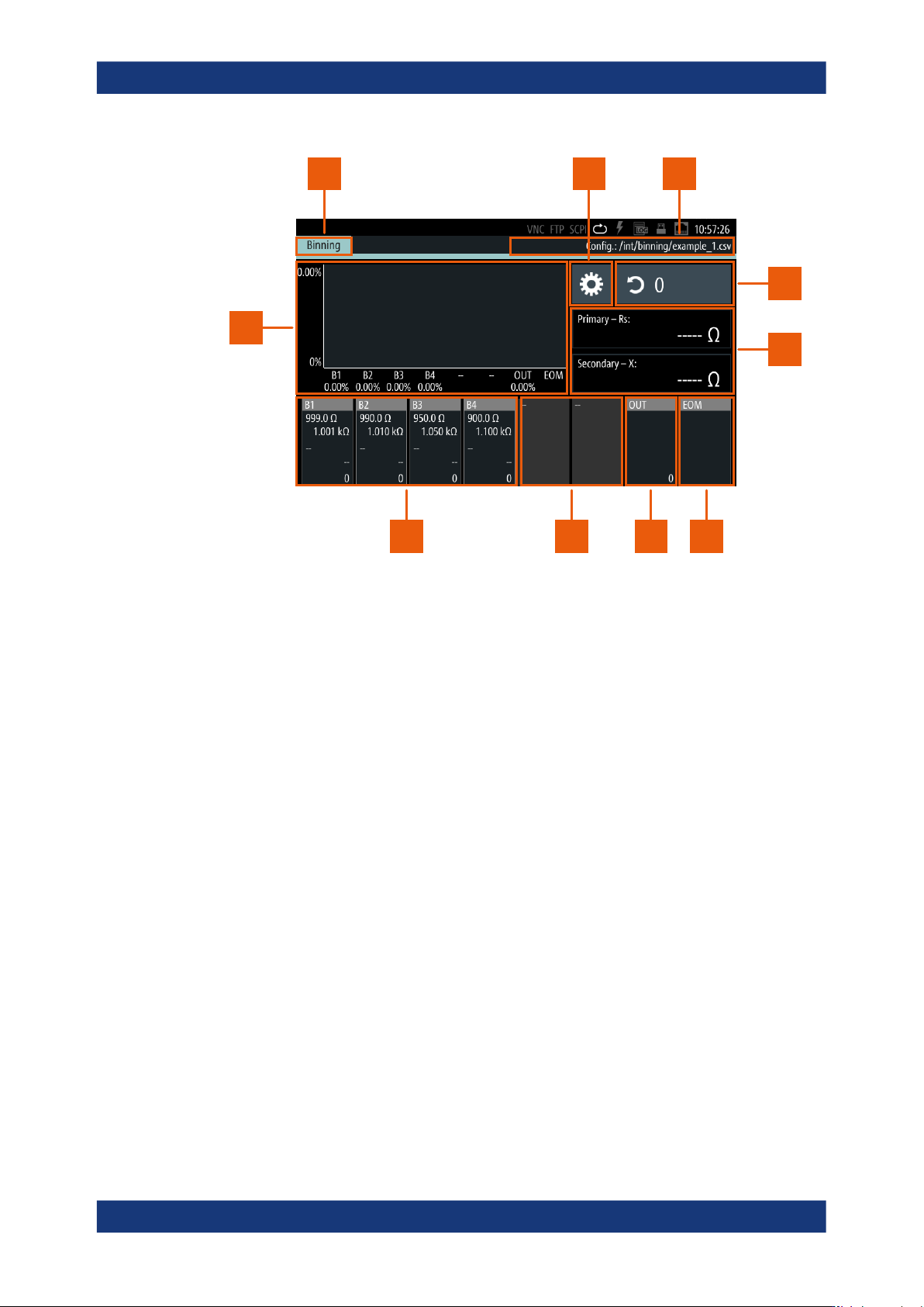
Figure 8-25: Binning measurement display and controls
1 = Measurement function indicator
2 = Settings softkey
3 = CSV file
4 = Counter
5 = Sorting characteristics
6 = End of measurement bin
7 = Out bin
8 = Unconfigured bin
9 = User-specified bins
10 = Histogram
8.8.5.1 About binning
To perform binning, the R&S LCX requires the bin configuration you must define and
upload in advance. In addition, you must configure the test signal (i.e. level and fre-
quency) and bias, compensation and measurement range settings before. Changing
these settings is not possible during a binning session.
To specify the bin configuration, you can define up to 8 categories according to 2 mea-
surement characteristics in a *.csv file, e.g. using a suitable application. Optionally,
you can configure the last bin to denote the end of each measurement, independently
of the result. Another control signal denotes if a component exceeds the specified lim-
its. You can assign these results to a bin also.
To upload the file, use a USB flash drive. When the binning function is enabled, the
R&S LCX measures the connected component initiated by a trigger signal. It indicates
the result, i.e. the corresponding bin on the screen, and also assigns a signal at one of
the 8 digital bin outputs.
Specific instrument functions
Instrument functions
R&S
®
LCX Series
112User Manual 1179.2260.02 ─ 08
Contents of the *.csv file:
●
Up to 2 measurement parameters
●
The measured value range of each of the two parameters for the individual bin.
●
The value ranges of the measurement parameters defined for the corresponding
categories (up to 8 bins).
●
How the limits are specified:
– Minimum and maximum values
– Nominal value and percentage deviation
– Nominal and deviation value
●
Additional signals you want to have assigned at the output, i.e. end of measure-
ment, out of bin, both).
With the binning function enabled, the R&S LCX switches to measurement mode "trig-
gered" automatically. The measurement starts with the first trigger signal. You can
either trigger the measurement manually, using the [Trig.] key at the front or by sending
the remote command *TRG. It is also possible to apply an external trigger signal to the
"Trigger Input" connector at the rear of the instrument.
During the binning measurements, the R&S LCX is permanently in the triggered mode
and cannot be disabled.
How to: see Section 8.8.5.5, "Configuring and using the binning function",
on page 116.
For details on the trigger modes, see the specifications document, section "Digital trig-
ger and control interfaces".
8.8.5.2 Assignment of the binning interface
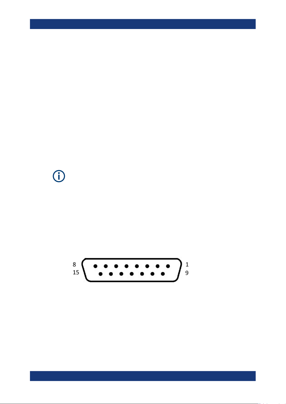
The digital I/O port of the binning interface is a 15-pole D-Sub female socket, including
eight data lines. The remaining pins provide digital input and output of control signals.
Figure 8-26: Digital I/O connector, front view
For details on the interface specification, see section "Digital trigger and control interfa-
ces" in the specifications document.
Specific instrument functions
Instrument functions
R&S
®
LCX Series
113User Manual 1179.2260.02 ─ 08
Table 8-2: Pin assignment
Pin Signal Direction Pin Signal Direction
1 - 8 Digital output sig-
nals 1 to 8.
The digital outputs
are active low.
OUT 11 - 13 GND OUT
9 Trigger signal input.
The falling edge of
an externally
applied signal ini-
tiates the trigger.
IN 14 + 3.3 V OUT
10 Digital input IN 15 + 12 V OUT
8.8.5.3 Binning settings
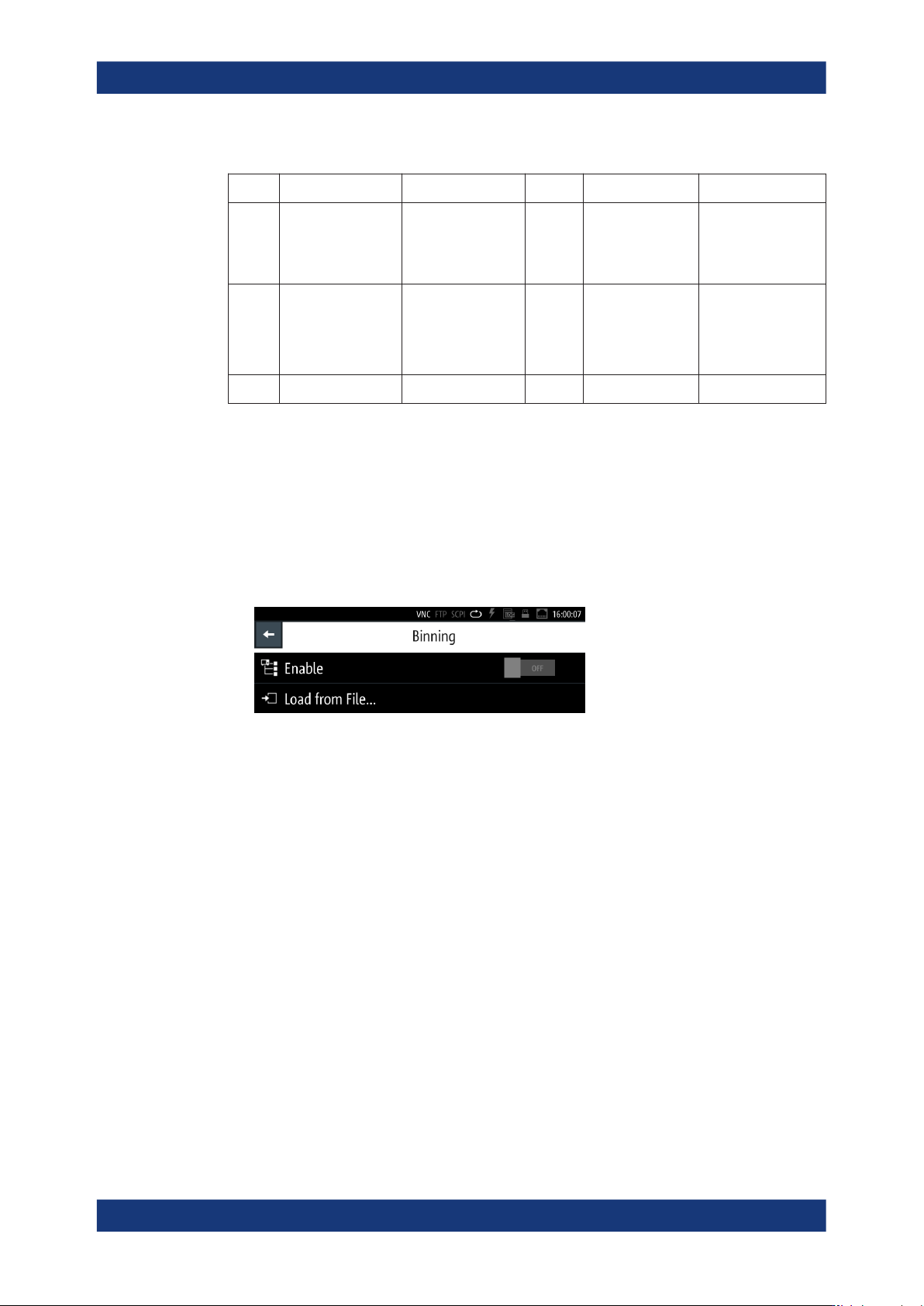
In the "Binning" menu, you can upload the binning file, and start the measurement.
Access:
1. Press the [settings] key at the front panel.
2. In the "Functions" tab, select "Binning".
Figure 8-27: Binning menu
In the initial softkey menu, you can load the binning file and activate the measure-
ment.
During the process, the main screen indicates the parameters related to the mea-
surement, and access to the bin configuration.
The required remote commands are described in Section 11.12, "HANDler subsystem",
on page 214.
Enabled....................................................................................................................... 113
Load From File............................................................................................................ 113
Enabled
Enables the sorting function.
The measurement starts with a trigger signal.
Remote command:
HANDler[:STATe] on page 216
Load From File
Accesses the file manager function to upload the binning configuration file.
Specific instrument functions