LCX_UserManual_en_08_1.pdf - 第156页
Network operation and remote control R&S ® LCX Series 156 User Manual 1 179.2260.02 ─ 08 See Remote control via SCPI for additional information on the characteristics, control commands and messages of the GPIB interf…

Network operation and remote control
R&S
®
LCX Series
155User Manual 1179.2260.02 ─ 08
driver. Using the VISA library, it supports service request trigger, and other specific
operations, similar to GPIB.
For control, you can use the SCPI terminal function of the R&S HMExplorer soft-
ware. This software also provides logging of measurement values, or graphical dis-
play.
●
CDC
(Communications Device Class, also known as VCP Virtual COM Port) is a proto-
col used for emulating serial ports over USB. Using the CDC protocol, you have to
install the USB VCP driver corresponding to the Windows operating system of the
controller PC, available for download on the Rohde & Schwarz product site at
www.rohde-schwarz.com/driver/lcx/.
To select the USB interface, see "Selecting the USB communication class protocol"
on page 172-
USB resource string
The resource string represents an addressing scheme that is used to establish a com-
munication session with the instrument. It is based on the instrument address and
some instrument- and vendor-specific information.
The USB resource string syntax is as follows:
USB::<vendor ID>::<product ID>::<serial number>[::INSTR]
USB
= denotes the used interface
<vendor ID> = is the manufacturer ID for Rohde & Schwarz
<product ID> = is the product identification of the instrument
<serial number> = is the individual serial number at the rear of the instrument
[::INSTR] = indicates the instrument resource class (optional)
To select the USB communication protocol, see "Selecting the USB communication
class protocol" on page 172.
Example:
USB::0x0AAD::0x01DD::100001
0x0AAD is the vendor ID for Rohde & Schwarz.
0x01DD is the product ID for the R&S LCX.
100001 is the serial number of the particular instrument.
10.2.3 GPIB interface (IEC/IEEE bus interface)
Option: R&S NG-B105 GPIB (IEC 625/IEE 488) bus interface
The GPIB interface is at the rear panel.
To control the R&S LCX over the GPIB bus, the instrument and the controller must be
connected with a GPIB bus cable. A GPIB bus card, the card drivers and the program
libraries for the programming language used must be provided in the controller.
Remote control interfaces and protocols

Network operation and remote control
R&S
®
LCX Series
156User Manual 1179.2260.02 ─ 08
See Remote control via SCPI for additional information on the characteristics, control
commands and messages of the GPIB interface.
GPIB address
The controller addresses the instrument with the GPIB bus channel, see Section 9.2.1,
"Interface settings", on page 125. GPIB provides channel addresses from 0 to 30. The
GPIB address is preset to 20 (factory-set), but you can adjust it according to your net-
work environment, see "Assigning the GPIB address manually" on page 173. An instru-
ment preset does not affect the GPIB address.
The GPIB resource string syntax is as follows:
GPIB:://<channel>[::INSTR]
GPIB
= denotes the used interface
<channel address> = the used channel
[::INSTR] = indicates the instrument resource class (optional)
If the VISA implementation supports the GPIB interface, you can optionally define the
VISA Instrument Control Resource (INSTR). It is used to define the basic operations
and attributes for a device, such as reading, writing, or triggering.
Example:
GPIB::28
28 is the selected GPIB bus channel.
10.2.4 Status reporting system
The status reporting system saves all information on the current operating state of the
instrument and the errors that have occurred. This information is saved in the status
registers and in the error queue. You can query the status of the registers remotely, i.e.
over the USB, GPIB or LAN interfaces with the commands of the Section 11.17, "STA-
Tus subsystem", on page 228.
Remote control interfaces and protocols
Network operation and remote control
R&S
®
LCX Series
157User Manual 1179.2260.02 ─ 08
10.2.4.1 Overview of the R&S LCX status registers
&
&
&
&
&
&
+
&
Status Byte
Service Request
to controller at transition
from 0 to 1
Error-/Event-Queue
Output-Queue
1
0
2
3
4
5
x
7
1
0
2
QUES
MAV
ESB
RQS/MSS
OPER
1
0
2
3
4
5
6
7
9
8
10
11
12
13
14
15
+
1
0
2
3
4
5
6
7
9
8
10
11
12
13
14
15
+
1
0
2
3
4
5
6
7
+
Standard Event
Status
Operation
Status
Questionable
Status
I-BIAS OV
Ext. V-BIAS OV
I-BIAS Analog FB Sat
LCUR Outamp DC OV
LCUR Outamp OT
Outamp disabled
LF-TIA OV
IQ-Mixer OV
CALibration*
STORage*
OCP*
EXPCalibration*
0
0
0
0
Operation Complete
Request Control
Query Error
Device Dependent Error
Execution Error
Command Error
User Request
Power On
CALibrating
SETTing*
RANGing*
UPDate
0
TRIGger
0
0
LIMit*
INTegrating*
LOGGing
LOCKed
INRush
0
0
0
0
0
Service Request Enable
1
0
2
3
4
5
6
7
9
8
10
11
12
13
14
15
+
0
Channel 1
Channel 2
Channel 3
Channel 4
Channel 5
Channel 6
Channel 7
Channel 8
0
0
0
0
0
0
0
* Master in multichannel mode can
query channel fan-out of these bits.
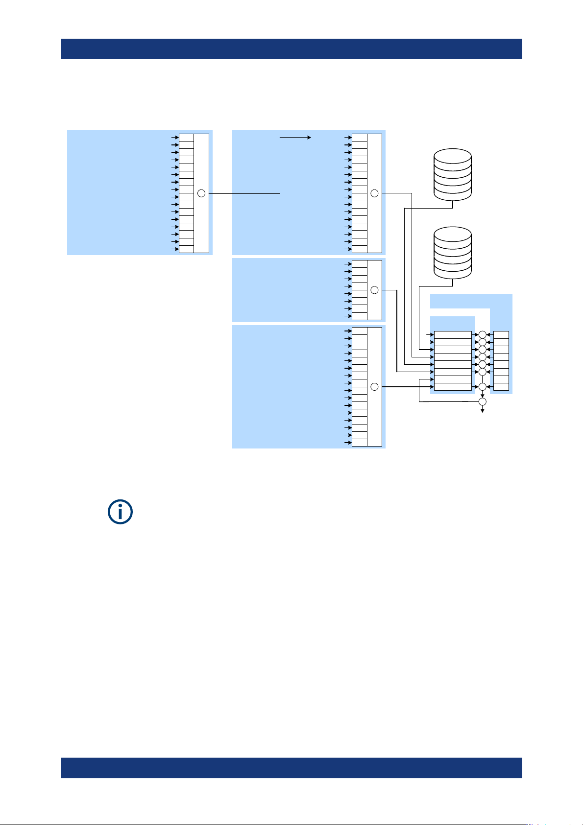
Figure 10-2: Graphical overview of the status registers hierarchy
The following sections describe the instrument-specific bit assignments of the opera-
tion status and the questionable status registers.
For more information, see:
●
Remote control via SCPI: provides general information on the status reporting sys-
tem of Rohde & Schwarz instruments. This document also provides information on
the standard event status register and the error queue.
●
Section 11.17, "STATus subsystem", on page 228: describes the corresponding
remote control commands of the status register
●
SCPI standard documentation for comprehensive information on the standard
10.2.4.2 Instrument-specific status operation register
The condition part contains information on currently executed actions. The event part
covers information on the actions performed since the last readout of the register.
Remote control interfaces and protocols