LCX_UserManual_en_08_1.pdf - 第71页
Instrument functions R&S ® LCX Series 71 User Manual 1 179.2260.02 ─ 08 Interfaces for external trigger signals Y ou have two options to apply an external trigger signal: ● T rigger Input connector Assign an external…

Instrument functions
R&S
®
LCX Series
70User Manual 1179.2260.02 ─ 08
8 Instrument functions
This section includes the basic instrument functions and operating modes. You can
configure these functions, either directly with the front panel controls or in the "Mea-
surement" menu.
8.1 Measurement mode
The R&S LCX LCR meter starts and performs a measurement according to the used
measurement mode:
●
Continuous
The instrument starts the measurement and perfoms it continuously.
Using this mode enables you to collect a series of measured values, e.g. to deter-
mine value deviations of the component sample, or to determine tolerance ranges.
●
Triggered
The instrument starts a measurement cycle controlled by a trigger event.
You can initiate a trigger event on the instrument with the [Trig.], with a remote con-
trol command or you can use an externally applied trigger signal.
The external trigger inputs are always enabled and thus start a measurement when
a trigger pulse is detected on one of the inputs. Signals received at the trigger input
during a measurement cycle take no effect until the current cycle is completed.
Using the manual trigger mode, you can e.g., measure a sample component at a
series of defined working points, by switching to the working points between the
measurements.
See:
●
"Using the manual trigger mode" on page 71.
●
"Using the continuous measurement mode" on page 71
●
"Interfaces for external trigger signals" on page 71
●
"Digital trigger and control interfaces" in the specifications document for details on
the signal level and specification of the interfaces.
Status display of the [Trig.] key LED
The LED of the [Trig.] indicates the status of the triggered mode:
●
Lighting permanently (triggered)
The measurement is running. The LED turns off after the measurement.
●
Blinking (armed)
The trigger is enabled with a delay time. After the time elapses, the measurement
starts, the LED lights permanently and turns off after the measurment.
●
Off (idle)
The trigger is disabled.
The R&S LCX indicates the trigger status also in the status bar, see Table 4-7.
Measurement mode

Instrument functions
R&S
®
LCX Series
71User Manual 1179.2260.02 ─ 08
Interfaces for external trigger signals
You have two options to apply an external trigger signal:
●
Trigger Input connector
Assign an external trigger signal to the Trigger Input connector at the rear panel.
The rising edge of the digital signal triggers the measurement at the TTL level of
+5 V.
●
Trigger signal input of the binning interface (option: R&S LCX-K107)
The binning interface provides the digital trigger signal at pin 9 of the digital I/O
port, see Binning > Assignment of the binning interface.
The falling edge of the signal triggers the measurement.
Using the continuous measurement mode
To measure a component sample in the default continuous measurement mode:
1. If the [Meas. Mode] key at the front panel lights up, press it to switch to continuous
mode.
The R&S LCX measures continuously and updates the readings according to
selected measurement speed, see "Speed" on page 80.
2. Press the [Hold] key to keep the range setting constant.
The [Hold] key lights up. You can use the function, e.g. to measure a batch of the
same components.
3. To disable automatic range selection, press the [Hold] key again.
The key no longer lights up.
Using the manual trigger mode
This example describes the steps to be taken, for measuring a component sample at a
series of working points, triggered manually:
1. Press the [Meas. Mode] key at the front panel.
The key lights up. The R&S LCX stops the continuous measurement, switches to
triggered mode and waits for a trigger event.
2. To set a time delay between the initiated trigger and the measurment start:
a) Press the [settings] key at the front panel.
b) Select the "Measurement".
c) Select "Trigger Delay".
d) Enter the time using the keypad on the screen.
e)
Confirm with
.
3. Press the home key to return to the measurement window.
4. To start the measurement, press the [Trig.] key at the front panel (Remote com-
mand: *TRG on page 185).
The key lights up. The R&S LCX performs one measurement cycle. When comple-
ted, the key turns off and the R&S LCX waits for the next trigger signal.
Measurement mode
Instrument functions
R&S
®
LCX Series
72User Manual 1179.2260.02 ─ 08
Note: The trigger icon also turns white during the measurement cycle. If you
have set a delay time, the trigger icon turns yellow until the delay time is elapsed.
5. Optionally, configure the next working point.
6. Repeat the steps until you have executed the measurement at all working points.
8.2 Display mode
The R&S LCX indicates the measurement results numerically and graphically.
Based on the measured values, the instrument calculates and derives the non-measur-
able parameters for display.
8.2.1 Display mode settings
Access:
1. To select the measurement result display, press the [home] key at the front panel.
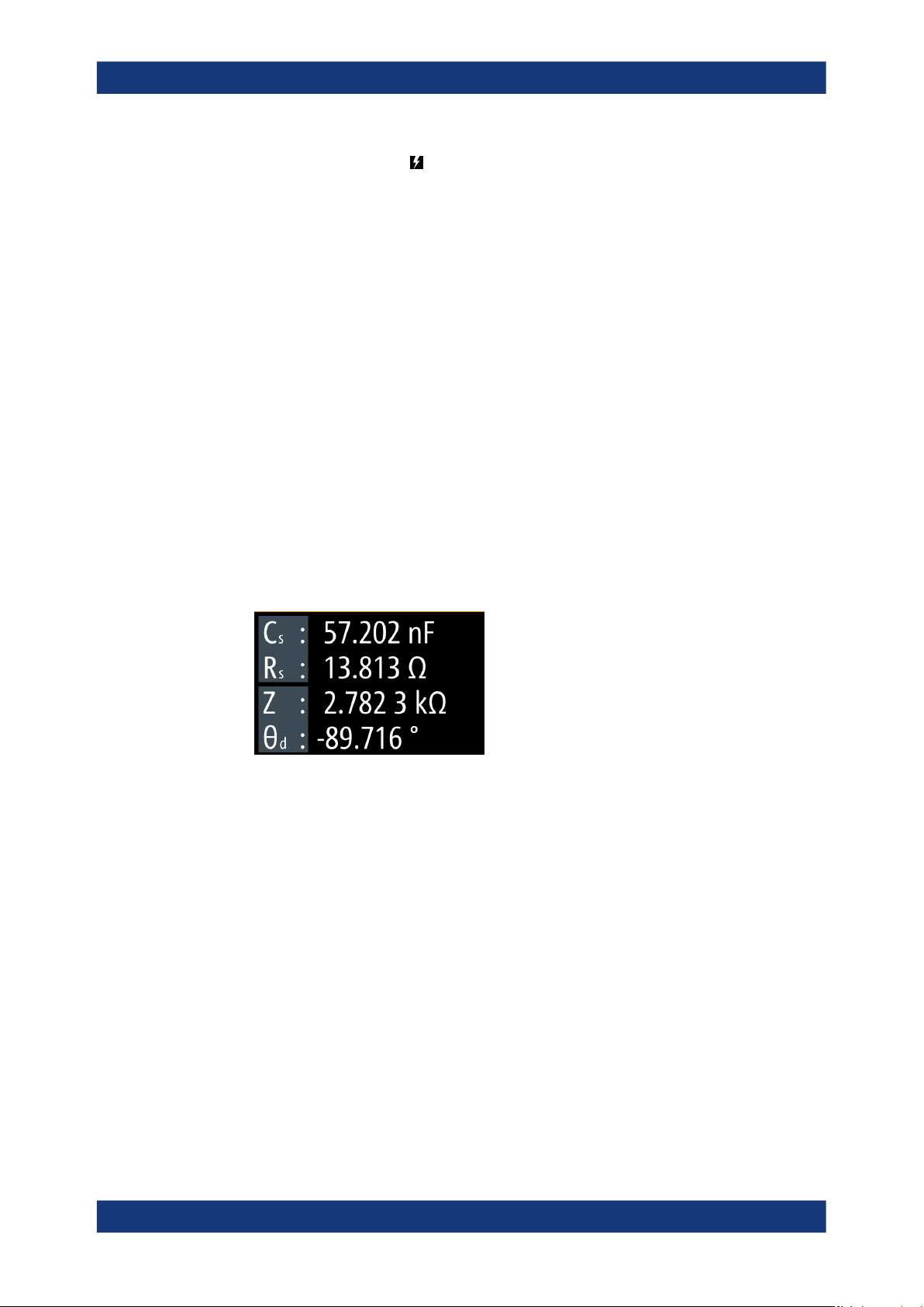
The numeric display shows the readings of four-measurement pairs by default.
Figure 8-1: Four measurement pairs display
2. Press the [Display Mode] key.
3. Pressing the key repeatedly, toggles between this view, the view with one mea-
surement pair and the graphical view.
Note: You can also access the graphical display in the "Functions" tab, see Sec-
tion 8.8, "Specific instrument functions", on page 93.
The results display shows the measurement results of the currently selected
parameters. The softkeys enable you to select the parameters for display accord-
ing to your measurement.
The required remote commands are described in: Section 11.11, "FUNCtion sub-
system", on page 209
How to: see Section 8.2.2, "Configuring the main view", on page 73.
<measurement pair>.....................................................................................................73
<measurement accuracy>.............................................................................................73
Display mode