LCX_UserManual_en_08_1.pdf - 第69页
Performing measurements R&S ® LCX Series 69 User Manual 1 179.2260.02 ─ 08 short secondary primary Figure 7-2: Leakage inductance measurement The inductance value of the primary winding measured with secondary windin…
Performing measurements
R&S
®
LCX Series
68User Manual 1179.2260.02 ─ 08
b) Connect both, the "N" and the "Common" test leads to the secondary circuit of
the transformer. Observe the polarity of the windings, if known. Both "Common"
test leads are equivalent.
The measurement starts and you can see the readings on the screen.
The transformer ratio "N-ΘNd" is the ratio between measured primary voltage and
measured secondary voltage.
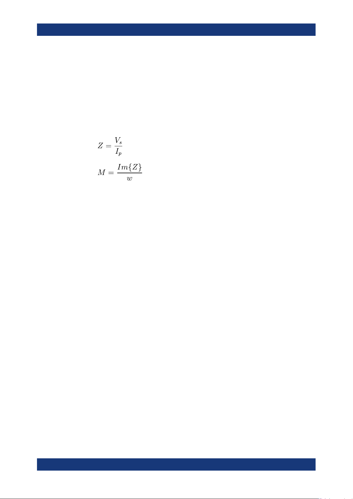
The mutual inductance "M-ΘNd" is calculated from measured primary current "I
p
"
and the measured secondary voltage "V
s
" as follows (Z is a virtual complex impe-
dance value):
Z
= virtual impedance
V
s
= measured voltage in secondary circuit
I
p
= measured current in primary circuit
M = mutual inductance
Im{Z} = imaginary part of impedance
ω
= angular frequency
If ΘNd is between 90° and 270°, the transformer inverts the signal. In this case, the
"M" result can display "RANGE" instead of a value. Invert the connection of one of
the windings to obtain a non-inverting setup and a valid measurement result
for "M".
Measuring the leakage inductance of a transformer
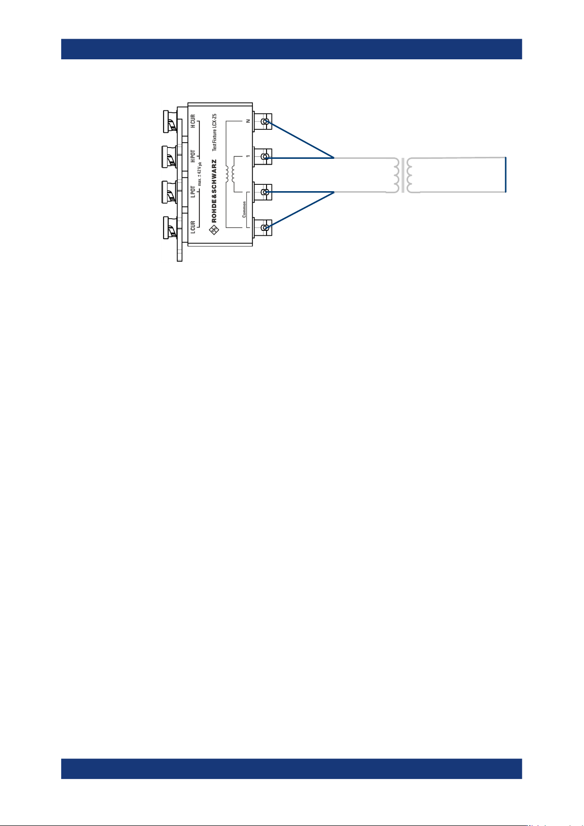
This example refers to a measurement of a transformer with the test fixture (R&S LCX-
Z5). You can also use only the included standard cables for inductance measurements
without the test adapter.
The connections and measurement settings are the same as for primary inductance
measurement, except that the secondary winding is shorted.
1. To select the inductance measurement (DUT component type), press the [L] key.
2. Set the measurement frequency, e.g. the mains frequency for a mains transformer.
3. Select the parameters for measurement results display as described under "Mea-
suring an inductor" on page 66.
4. Short-circuit the secondary winding of the transformer.
Performing measurements
R&S
®
LCX Series
69User Manual 1179.2260.02 ─ 08
short
secondaryprimary
Figure 7-2: Leakage inductance measurement
The inductance value of the primary winding measured with secondary winding
shorted corresponds to the primary leakage inductance.
To measure the secondary leakage inductance, connect the secondary winding
instead of the primary to the R&S LCX-Z5 and short circuit the primary winding.

Instrument functions
R&S
®
LCX Series
70User Manual 1179.2260.02 ─ 08
8 Instrument functions
This section includes the basic instrument functions and operating modes. You can
configure these functions, either directly with the front panel controls or in the "Mea-
surement" menu.
8.1 Measurement mode
The R&S LCX LCR meter starts and performs a measurement according to the used
measurement mode:
●
Continuous
The instrument starts the measurement and perfoms it continuously.
Using this mode enables you to collect a series of measured values, e.g. to deter-
mine value deviations of the component sample, or to determine tolerance ranges.
●
Triggered
The instrument starts a measurement cycle controlled by a trigger event.
You can initiate a trigger event on the instrument with the [Trig.], with a remote con-
trol command or you can use an externally applied trigger signal.
The external trigger inputs are always enabled and thus start a measurement when
a trigger pulse is detected on one of the inputs. Signals received at the trigger input
during a measurement cycle take no effect until the current cycle is completed.
Using the manual trigger mode, you can e.g., measure a sample component at a
series of defined working points, by switching to the working points between the
measurements.
See:
●
"Using the manual trigger mode" on page 71.
●
"Using the continuous measurement mode" on page 71
●
"Interfaces for external trigger signals" on page 71
●
"Digital trigger and control interfaces" in the specifications document for details on
the signal level and specification of the interfaces.
Status display of the [Trig.] key LED
The LED of the [Trig.] indicates the status of the triggered mode:
●
Lighting permanently (triggered)
The measurement is running. The LED turns off after the measurement.
●
Blinking (armed)
The trigger is enabled with a delay time. After the time elapses, the measurement
starts, the LED lights permanently and turns off after the measurment.
●
Off (idle)
The trigger is disabled.
The R&S LCX indicates the trigger status also in the status bar, see Table 4-7.
Measurement mode