LCX_UserManual_en_08_1.pdf - 第49页
Measurement basics R&S ® LCX Series 49 User Manual 1 179.2260.02 ─ 08 5 Measurement basics The following graph shows the capacitive and inductive parts of passive components during impedance measurement in dependency…

Getting started
R&S
®
LCX Series
48User Manual 1179.2260.02 ─ 08
b) Press the [rotary knob].
The selection editor opens.
c) Turn the knob to scroll within the list.
d) Press the [rotary knob] again to confirm your selection.
6. To access the main menus and subdialogs, use the functionality of the [rotary
knob] and the [◀] or [▶] keys the same way.
Entering alphanumeric parameters
If a field requires alphanumeric input, you can use the on-screen keyboard to enter let-
ters and (special) characters.
Access and control are similar as described above.
4.4.3 Remote control
In addition to operating the R&S LCX directly on the instrument, it is also possible to
operate and control it from a remote PC.
Remote control interfaces
The R&S LCX provides several interfaces for remote control:
●
Ethernet (LAN) interface
●
USB standard interface
●
IEE-488 bus interface (GPIB) (option: R&S NG-B105)
For detailed information on how to configure the remote control interfaces, see Sec-
tion 10, "Network operation and remote control", on page 149.
See Section 4.1.7, "Connecting to LAN", on page 24 for an example on how to set up a
LAN connection for remote control.
Instrument control
Measurement basics
R&S
®
LCX Series
49User Manual 1179.2260.02 ─ 08
5 Measurement basics
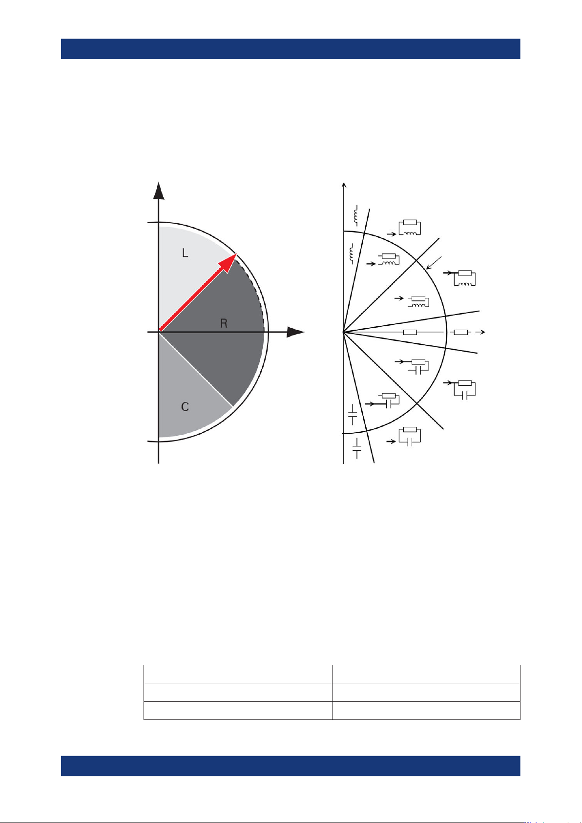
The following graph shows the capacitive and inductive parts of passive components
during impedance measurement in dependency on the frequency and the phase shift.
phase angle
above 45 ° = L
below -45 ° = C
Real axis
Imaginary axis jX
R
Q = D = 1
Q = D = 1
Q = 500
D = 0.002 Ω
|Z| = 1000 Ω
Q = 500
D = 0.002 Ω
Q = 500
D = 0.002 Ω
Q = 500
D = 0.002 Ω
Figure 5-1: Phase angle and integral sections
L = inductance
R = resistance
C = capacitance
|Z| = impedance
D = dissipation factor
Q = quality factor
5.1 Impedance measurement parameters in general
The following table outlines the basic parameters and their definitions:
Table 5-1: Basic parameters and definitions
Parameter (designation and [unit]) Definition
Z (Ω) Impedance
|Z| (Ω) Magnitude of Z
Impedance measurement parameters in general
Measurement basics
R&S
®
LCX Series
50User Manual 1179.2260.02 ─ 08
R (Ω) Resistance
X
s
(Ω) Reactance
Y (S) Admittance
|Y| (S) Magnitude of Y
G
p
(S) Equivalent parallel conductance measured with par-
allel-equivalent circuit model
B
p
(S) Susceptance
Imaginary part of Y
Q Quality factor (inverse of D)
D or tanδ Dissipation factor
Θ
r
(rad) Phase angle of impedance/admittance (radian)
Θ
d
(°) Phase angle of impedance/admittance (degree)
φ (rad, °) Phase angle of Y
C
s
(F) Capacitance value measured with series-equivalent
circuit model
C
p
(F) Capacitance value measured with parallel-equiva-
lent circuit model
L
s
(H) Inductance value measured with series-equivalent
circuit model
L
p
(H) Inductance value measured with parallel-equivalent
circuit model
R
s
or ESR (Ω) Equivalent series resistance measured with series-
equivalent circuit model
R
p
(Ω) Equivalent parallel resistance measured with paral-
lel-equivalent circuit model
R
DC
(Ω) Direct current resistance
V
DC
(V) Direct current voltage
I
DC
(A) Direct current electricity
q
d
(°) Phase angle of impedance/admittance (degree)
q
r
(rad) Phase angle of impedance/admittance (radian)
5.2 Impedance measurement parameters of the R&S LCX
In addition to the characterization of the resistance, inductance and capacity of passive
components, the R&S LCX determines parameters like the quality factor (Q), the dissi-
pation factor (D), the phase angle (Θ), and the complex values of the impedance (Z)
and the admittance (Y).
The following tables show the parameter pairs that you can select for display.
Impedance measurement parameters of the R&S
LCX