LCX_UserManual_en_08_1.pdf - 第39页
Getting started R&S ® LCX Series 39 User Manual 1 179.2260.02 ─ 08 For detailed information, see Section 8.2, "Display mode" , on page 72. 3 4 6 2 1 5 Figure 4-7: Example of screen display 1 = Configuration…
Getting started
R&S
®
LCX Series
38User Manual 1179.2260.02 ─ 08
Using various finger gestures you can select any user interface element, set
parameters in dialogs, enter data using online keypads, or scroll within a dialog.
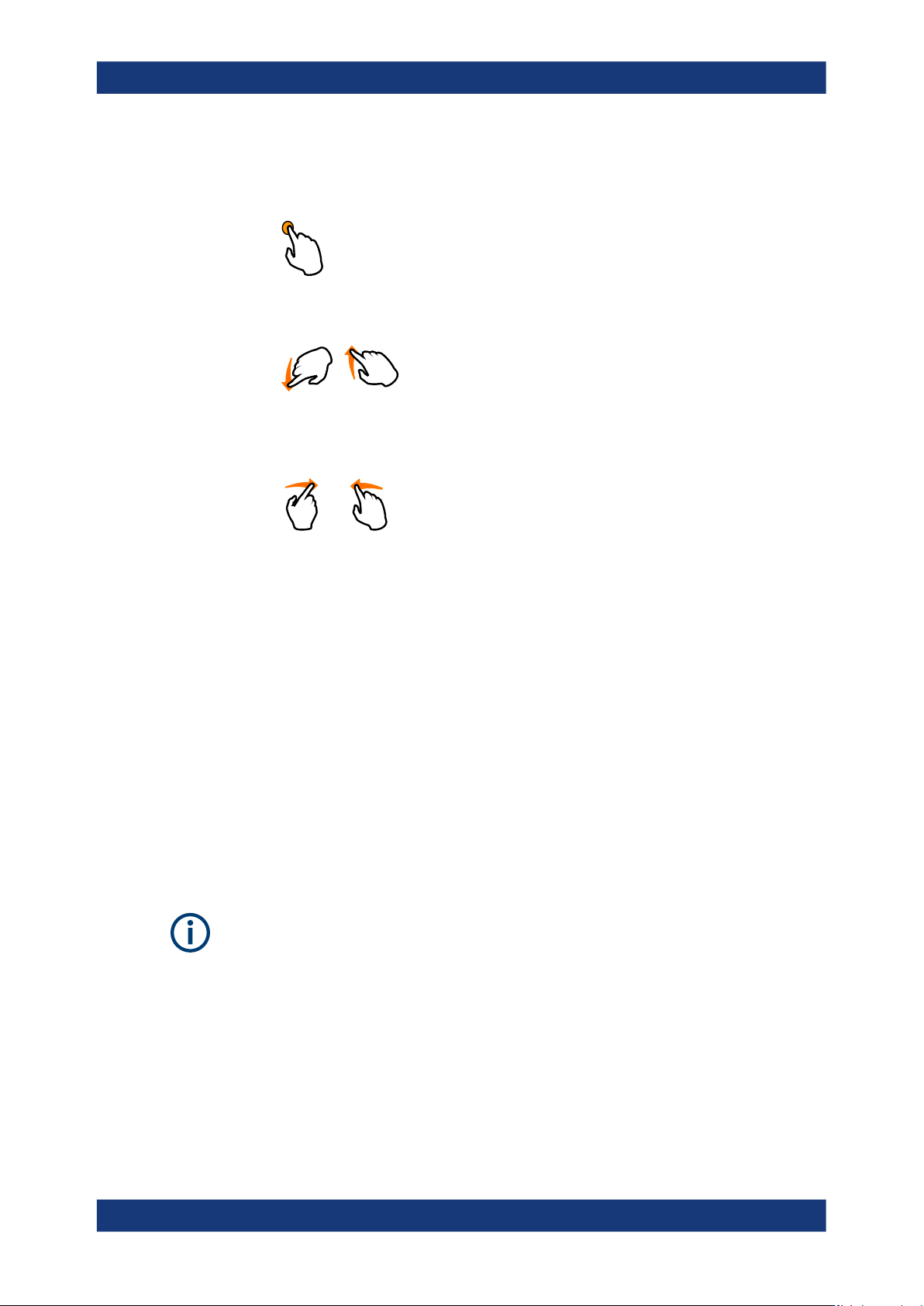
– Tapping
Touch quickly: selects a parameter or provokes an action.
– Swiping
Touch and swipe: Scrolls through the contents of a display element larger than
the screen, e.g. a menu list.
– Dragging
Touch and drag: Shifts the contents from one position to another on the display.
By dragging your finger over a diagram, you can pan the displayed area of the
diagram to show results that were previously out of view.
●
System, measurement and function keys
The front panel hardkeys provide nearly all functions and controls to operate the
instrument in the classic way, without using the touchscreen.
You can access the main functions and parameters, measurement and display
modes and configure general instrument settings. When selected, i.e. a function is
active, the corresponding function key lights up white.
●
Navigation controls
The navigation controls include a [rotary knob] and right [▶], left [◀] keys.
The rotary knob allows you to navigate on the home screen or in dialogs, and to
set parameters. The [◀] [▶] move the cursor in the entry fields.
This manual describes the manual interaction with the instrument using the touch-
screen. It mentions the alternative methods using the keys on the instrument or the on-
screen keypads if it deviates from the standard operating procedures.
Throughout the manual, the term "select" refers to any of the described methods, i.e.
using a finger on the touchscreen or a key on the instrument or on a keyboard.
For basic instructions on how to control the R&S LCX, see Section 4.4.2.2, "Accessing
the functionality", on page 45.
4.4.2.1 Understanding the display information
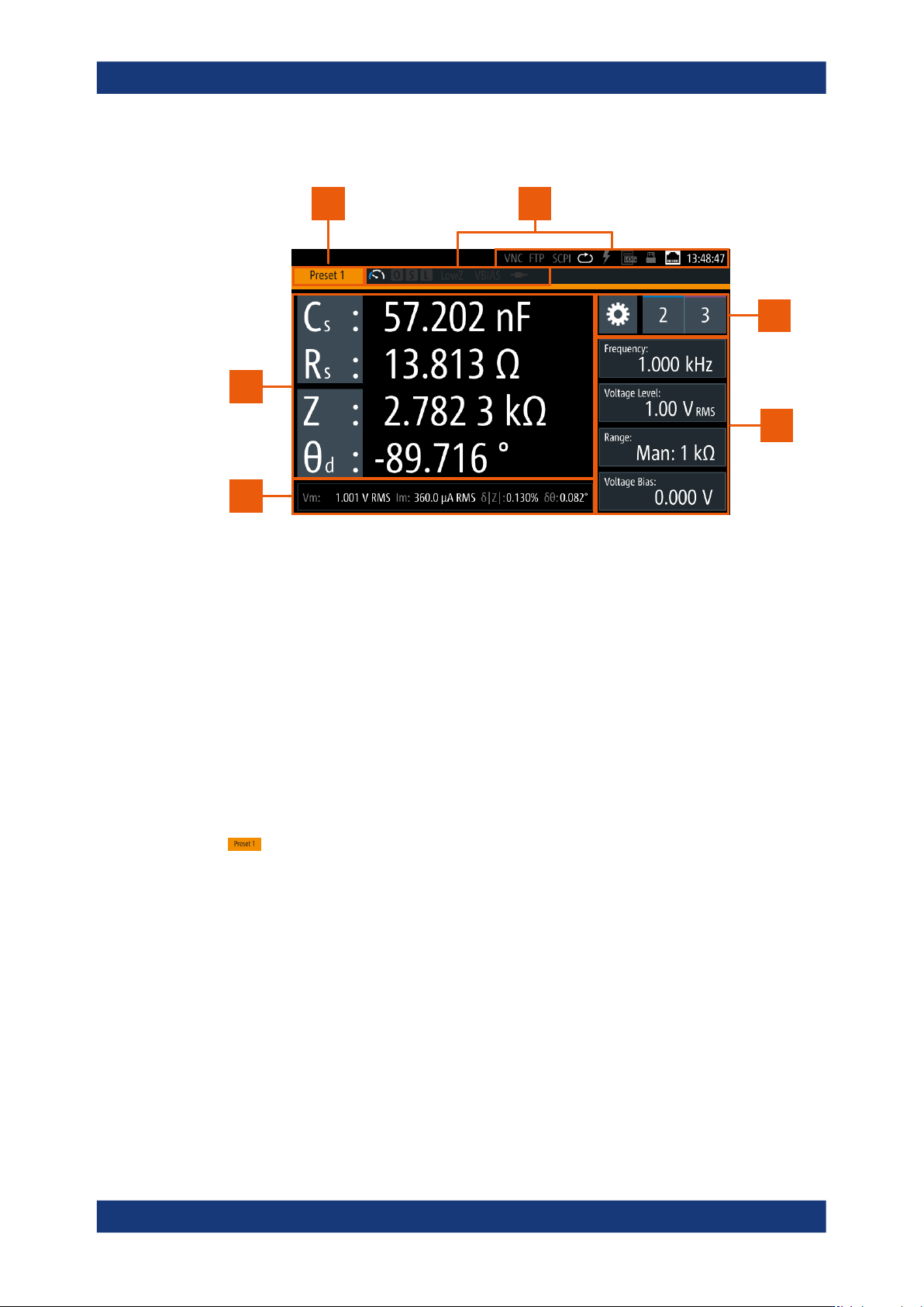
The initial display screen shows the measurement result window, status information
and general settings at the top. The main area displays the measurement results,
depending on the selected measurement and display mode.
Instrument control
Getting started
R&S
®
LCX Series
39User Manual 1179.2260.02 ─ 08
For detailed information, see Section 8.2, "Display mode", on page 72.
3
4
6
21
5
Figure 4-7: Example of screen display
1 = Configuration preset indicator, see "Configuration preset indicator" on page 39
2 = Status bars, see "Status bar" on page 39
3 = Settings softkey and configuration preset softkeys, see "Settings softkey" on page 42, "Configuration
preset softkeys" on page 42
4 = Signal parameters, see "Signal parameters" on page 42
5 = Test signal monitor, see "Test signal monitor" on page 42
6 = Measurement parameters and results, see "Measurement parameters and results" on page 43
The following sections explain the information areas as labeled.
Configuration preset indicator
The R&S LCX enables you to set up to three different measurement configurations and
assign them as favorites with the "Configuration preset softkeys" on page 42. The
indicator displays the currently active preset configuration.
(Preset 1/2/3) displays the currently active preset configuration.
Status bar
You can see two status bar lines. The status bar in the upper line on the right, referred
to as the instrument status bar, indicates icons, which represent the states of connec-
tions, remote control communication and modes. The status bar to the right of "Preset"
is referred to as the measurement status bar. Its icons indicate measurement modes
and states.
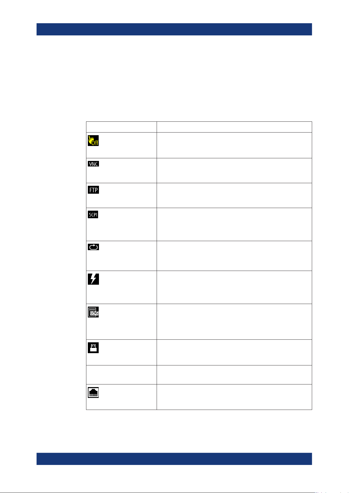
Instrument status bar
The instrument status bar refers to the general instrument configuration and modes,
see Table 4-7 for information on the icons.
Instrument control
Getting started
R&S
®
LCX Series
40User Manual 1179.2260.02 ─ 08
The color of the symbols indicates the status of, e.g. a function, connection or a proc-
ess:
●
white - enabled, or running
●
gray - disabled
●
red - faulty
●
yellow - denotes a specific status
Table 4-7: Instrument status bar
Indicator Description
Touchscreen
Indicates that the touchscreen is locked.
See Section 9.3, "User button", on page 127
Virtual Network Computing
White indicates that the VNC service is enabled for remote access over
LAN.
See "Remote operation (VNC)" on page 150.
File Transfer Protocol
White indicates that the remote access to the file system over LAN is
enabled.
See "Remote file access (FTP)" on page 151.
(Remote control with SCPI
commands)
Indicates the status when working with remote control commands:
●
single white flash: SCPI command received successfully
●
red: a remote control error has occurred, entered in the SCPI error
queue
●
gray: no SCPI communication
Continuous measurement
mode
Indicates the status of the continuous mode:
●
white: continuous measurement is running
●
gray: continuous measurement mode disabled
See Section 8.1, "Measurement mode", on page 70
Triggered measurement mode
Indicates the trigger status:
●
white: measurement is triggered and running
For fast measurements, the icon lights up only briefly.
●
gray: waiting for the next trigger event and triggered disabled
●
yellow: waiting for a trigger event during a trigger delay
Logging
Indicates the logging state:
●
white: data logging is running
●
red: a logging error has occurred
●
gray: logging is disabled
See Section 8.8.3, "Logging", on page 101
USB host interface
White indicates that a connected USB memory device is in use.
See Section 4.1.8, "Connecting USB devices", on page 25.
USB device interface The USB remote control connection is established.
See "Establishing a USB remote control connection" on page 168.
LAN interface
The R&S LCX is connected to LAN.
See Section 4.1.7, "Connecting to LAN", on page 24.
Instrument control