LCX_UserManual_en_08_1.pdf - 第23页
Getting started R&S ® LCX Series 23 User Manual 1 179.2260.02 ─ 08 b) Press the plastic lock on the bottom of the fuse holder inwards using a screw- driver (with a blade width of approximately 2 mm). A narrow guide o…

Getting started
R&S
®
LCX Series
22User Manual 1179.2260.02 ─ 08
Replacing the external bias fuse
The bias voltage input of the R&S LCX is protected by a fuse of type IEC 60127-2/5-
F0.5L/250V (order no. 0009.5463.00). The externally accessible fuse is at the rear
panel.
To check and exchange the external bias fuse:
1.
NOTICE! Risk of instrument damage. Malfunction of the fuse that protects the bias
voltage input from overload can damage the circuitry of the instrument.
Do not use either fuse type other than specified, nor a defective fuse, and never
short-circuit the fuse.
Make sure that you have disconnected the R&S LCX from the mains.
2. Check the condition of the external bias fuse.
3. If necessary, install the fuse type required for the external bias voltage.
a) Unscrew the fuse holder with a suitable screwdriver.
b) Pull out the fuse holder.
c) Replace the fuse by a fuse of the specified type.
d) Insert the fuse holder into the external bias inlet.
When inserting the fuse holder, press it slightly and tighten it.
Replacing the line fuse
The product is protected by one fuse of type IEC 60127-2/5-T2.0H/250V
(order no. 0020.7546.00). The externally accessible fuse is part of the IEC socket of
the power supply at the rear panel.
To exchange the line fuse:
1. Check the available supply voltage.
The mains voltage must be within the voltage range as denoted on the instrument.
The label is at the rear panel, on the left of the "AC power" connector and power
switch.
The power supply module covers a wide power supply range and normally does
not require adjustment.
2. If the power supply exceeds the permissible range, contact Rohde & Schwarz cus-
tomer service.
3.
WARNING! The fuse is part of the AC power supply. Handling the fuse while the
power is on can lead to electric shock.
If necessary, exchange the fuse required for the supply voltage.
4. Before changing the fuse:
a) Set the switch on the power supply to position [0].
b) Disconnect the R&S LCX from the power source.
5. Replace the line fuse.
a) Unplug the power cable.
Preparing for use

Getting started
R&S
®
LCX Series
23User Manual 1179.2260.02 ─ 08
b) Press the plastic lock on the bottom of the fuse holder inwards using a screw-
driver (with a blade width of approximately 2 mm).
A narrow guide on the bottom of the fuse holder denotes the insertion point.
When unlocking the mechanism, compression springs automatically push the
fuse holder outwards.
c) Pull out the fuse holder.
d) Check the condition of the fuse.
e) Replace the fuse by a fuse of the specified type.
A label next to the fuse holder also indicates the fuse type and its characteris-
tics.
f) Note: The protruding contact springs must not be deformed. Align the fuse
holder with the guide bar facing the socket.
Carefully slide the fuse holder against the spring pressure into the slot until the
plastic lock latches.
Connecting to power
To connect the instrument to the mains:
1. Check the available supply voltage.
The mains voltage must be within the voltage range as denoted on the instrument.
The label is at the rear panel, on the left of the "AC power" connector and power
switch.
The power supply module covers a wide power supply range and normally does
not require adjustment.
2. If the power supply exceeds the permissible range, contact Rohde & Schwarz cus-
tomer service.
3.
If necessary, ground the instrument using the grounding connection
.
A ground connector socket is at the front panel to connect a ground cable with a
banana plug.
As an alternative, a ground terminal at the rear panel enables you to connect a
ground cable firmly with a screw:
a) At the rear panel, unscrew the screw of the ground terminal using a cross-
recess screw driver.
b) Attach a ground cable with a ring terminal and pass the screw through it.
c) Fasten the screw.
d) Connect the cable to the ground.
4. Plug the AC power cable into the "AC power" connector.
The power supply switch connector is at the rear panel. Only use the power cable
delivered with the R&S LCX.
5. Plug the AC power cable into a power outlet with ground contact.
The required ratings are listed next to the AC connector and in the specifications
document.
Preparing for use
Getting started
R&S
®
LCX Series
24User Manual 1179.2260.02 ─ 08
4.1.7 Connecting to LAN
Establishing the LAN connection
The R&S LCX provides Ethernet (LAN) connectivity. Provided the corresponding rights
are assigned, you can use these interfaces for remote control and data transfer from a
controller PC. The controller PC must also be connected in the network.
The "LAN" connector is at the rear panel.
To connect the R&S LCX to the LAN:
1. Connect the "LAN" socket using an RJ-45 cable to the LAN.
By default, the R&S LCX configuration uses DHCP that assigns the IP address
automatically.
2.
NOTICE! If the R&S LCX cannot obtain an IP address automatically, or cannot
establish the connection, the icon in the status bar turns red.
Possible reasons are that the LAN does not support DCHP or requires a specific
TCP/IP configuration, or that the connection is missing.
To troubleshoot the problem, proceed as follows:
a) Check if you have connected both the R&S LCX and the controller PC to the
LAN.
b) Consult your network administrator to request support and an IP address, if
necessary.
c) If necessary, assign the IP address manually as described in "Assigning the
LAN interface addresses manually" on page 169.
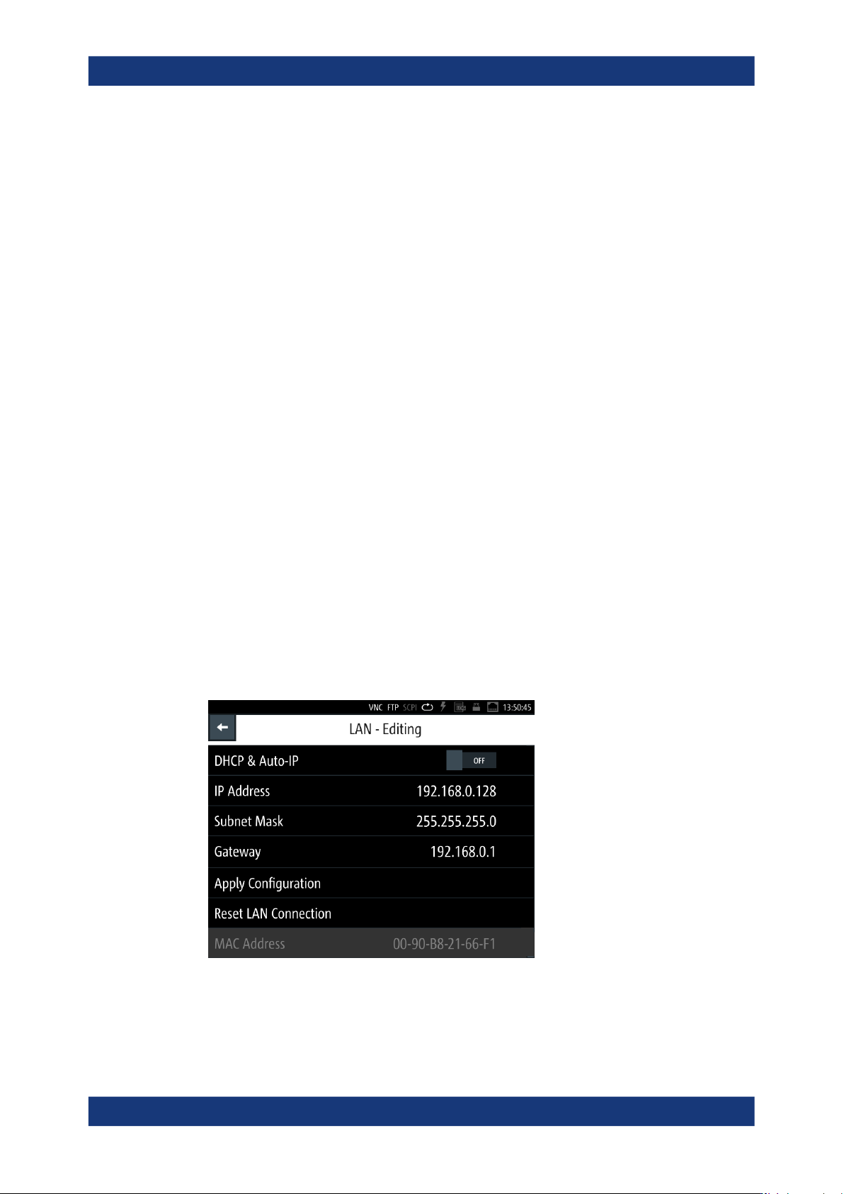
If switched on and connected, the R&S LCX indicates the address information and
LAN parameters in the "Ethernet Settings dialog".
Figure 4-1: LAN settings dialog
Preparing for use