LCX_UserManual_en_08_1.pdf - 第168页
Network operation and remote control R&S ® LCX Series 168 User Manual 1 179.2260.02 ─ 08 Establishing the LAN connection The R&S LCX provides Ethernet (LAN) connectivity . Provided the corresponding rights are as…
Network operation and remote control
R&S
®
LCX Series
167User Manual 1179.2260.02 ─ 08
Note: If you change the "USB Class", you must reboot the instrument to load the corre-
sponding USB driver, see "Selecting the USB communication class protocol"
on page 172.
Remote command:
INTerfaces:USB:CLASs on page 235
10.3.6 GPIB settings
Option: R&S NG-B105 GPIB (IEC 625/IEE 488) bus interface
For remote control over GPIB, you can address the R&S LCX over a channel address.
Access:
1. Press the [settings] key at the front panel.
2. In the device settings menu, select "Interfaces".
3. Select "GPIB Address".
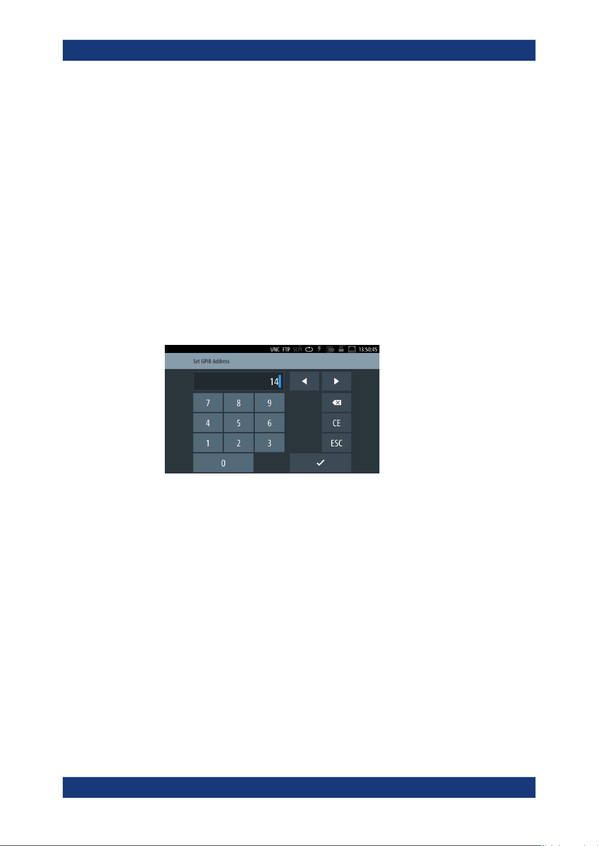
Figure 10-8: GPIB address on-screen keypad
The controller must address the instrument with the GPIB bus address.
GPIB Address
Set the GPIB channel address of the connected instrument.
About: see Section 10.2.3, "GPIB interface (IEC/IEEE bus interface)", on page 155
How to: see "Assigning the GPIB address manually" on page 173
10.4 Connecting the R&S LCX for remote access
This section briefly explains how to set up the remote control connections for the inter-
faces provided by the R&S LCX.
Connecting the R&S
LCX for remote access
Network operation and remote control
R&S
®
LCX Series
168User Manual 1179.2260.02 ─ 08
Establishing the LAN connection
The R&S LCX provides Ethernet (LAN) connectivity. Provided the corresponding rights
are assigned, you can use these interfaces for remote control and data transfer from a
controller PC. The controller PC must also be connected in the network.
The "LAN" connector is at the rear panel.
To connect the R&S LCX to the LAN:
1. Connect the "LAN" socket using an RJ-45 cable to the LAN.
By default, the R&S LCX configuration uses DHCP that assigns the IP address
automatically.
2.
NOTICE! If the R&S LCX cannot obtain an IP address automatically, or cannot
establish the connection, the icon in the status bar turns red.
Possible reasons are that the LAN does not support DCHP or requires a specific
TCP/IP configuration, or that the connection is missing.
To troubleshoot the problem, proceed as follows:
a) Check if you have connected both the R&S LCX and the controller PC to the
LAN.
b) Consult your network administrator to request support and an IP address, if
necessary.
c) If necessary, assign the IP address manually as described in "Assigning the
LAN interface addresses manually" on page 169.
Establishing a USB remote control connection
You can use the USB B interface for remote control and data transfer from a controller
PC. Remote control over USB requires the VISA library, or the corresponding TMC or
CDC protocol drivers. The controller PC and the instrument must be connected at the
USB B interface.
The USB B connector is at the rear panel.
To connect the R&S LCX to the controller PC:
► Connect the USB B connector using a double-shielded USB cable to the controller
PC.
VISA detects and configures the instrument automatically when the USB connec-
tion is established. You do not have to enter an address string or install a separate
driver.
Establishing the GPIB remote control connection
Option: R&S NG-B105 GPIB (IEC 625/IEE 488) bus interface
You can use the GPIB bus interface for controlling the instrument remotely.
The USB B connector is at the rear panel.
Connecting the R&S
LCX for remote access

Network operation and remote control
R&S
®
LCX Series
169User Manual 1179.2260.02 ─ 08
To connect the R&S LCX to the controller PC:
1. Connect the IEC 625/IEEE 488 connector of the R&S LCX to the controller PC with
a double-shielded GPIB bus interface cable.
2. Configure the settings for remote control as described in "Assigning the GPIB
address manually" on page 173.
The controller must address the instrument with the GPIB bus address, see Sec-
tion 10.2.3, "GPIB interface (IEC/IEEE bus interface)", on page 155.
10.5 Adjusting interface addresses
Depending on the network capabilities, the TCP/IP address information for the instru-
ment can be obtained in different ways.
●
If the network supports DHCP (dynamic host configuration protocol), the address
information is assigned automatically. This mode enables you to establish a physi-
cal connection to the LAN without any additional instrument configuration.
●
If the network does not support DHCP, or if the instrument is set to use an alternate
TCP/IP configuration, you must set the addresses manually, see "Assigning the
LAN interface addresses manually" on page 169.
●
SCPI Raw Port
As an alternative, you can establish a raw TCP/IP connection using sockets for
sending raw SCPI commands to the instrument. To configure the connection,
assign the port, and, if necessary, the host name of the instrument, see "Assigning
the SCPI raw port and hostname manually" on page 172.
Assigning the LAN interface addresses manually
If the network provides DHCP, this protocol assigns the IP address automatically
(default setting). But you can also assign the address manually, if necessary. It is
assumed that you have connected controller PC and the instrument, see "Establishing
the LAN connection" on page 24.
To assign the IP addresses for the LAN interface manually:
1.
NOTICE! Risk of network failure. Connecting to the network can cause network
failure. Errors can affect the entire network.
Consult your network administrator before performing the following tasks:
● Connecting the instrument to the network
● Configuring the network
● Changing IP addresses
2. Access: see 159
3.
Turn "DHCP & Auto-IP'".
Adjusting interface addresses