LCX_UserManual_en_08_1.pdf - 第31页
Getting started R&S ® LCX Series 31 User Manual 1 179.2260.02 ─ 08 T able 4-6: Navigation controls Key Assigned functions [Auto] Enables the automatic selection of the measurement function. [Hold] Freezes the measure…
Getting started
R&S
®
LCX Series
30User Manual 1179.2260.02 ─ 08
Table 4-2: Navigation controls
Key Assigned functions
[Rotary knob] Selects, enables or confirms settings.
[◀] / [▶] Moves the cursor in the entry fields.
[Back] Returns to a previous level in the menus, or closes a view.
Measurement mode keys
The measurement controls enable you to select the measurement mode and view of
the representation of the measurement readings.
Table 4-3: Measurement mode controls
Key Assigned functions
[Meas. Mode] Selects either continuous or triggered measurement mode.
[Display Mode] Selects the display of measurement readings.
Function keys
The keys in the function panel select the parameters for the measurement.
Table 4-4: Measurement function controls
Key Assigned functions
[L] Selects the function for measuring inductance.
[C] Selects the function for capacity measurement.
[R] Selects the measurement for a resistor.
[Transformer] Selects the transformer measurement.
Settings keys
The keys in the settings panel enable you to select measurement ranges and addi-
tional parameters for executing the measurement.
Table 4-5: Measurement function controls
Key Assigned functions
[Freq.] Sets the signal frequency.
[Range] Selects the impedance range.
[Level] Sets the level.
[Comp.] Opens the "Open/Short/Load Correction" dialog for quick access.
[Bias Level] Sets the bias voltage and current.
[Bias Enable] Enables internal or external bias.
Measurement control keys
These keys provide control during the measuring procedure.
Instrument tour
Getting started
R&S
®
LCX Series
31User Manual 1179.2260.02 ─ 08
Table 4-6: Navigation controls
Key Assigned functions
[Auto] Enables the automatic selection of the measurement function.
[Hold] Freezes the measurement range on the screen indicated with the prefix
"Hold:" at the range value.
[Trig.] Triggers a measurement manually.
POWER On/Standby key
The [On/Standby] key switches the instrument from the standby to the ready state or
vice versa.
The [On/Standby] lights green when the instrument is switched on, see Section 4.1.10,
"Switching on or off", on page 27.
4.2.1.3 Connectors
The measurement input connectors and the USB connector are on the front panel.
L CUR, L POT, H CUR, H POT
Four BNC sockets:
●
"L CUR" (low current): signal output for series measurements (signal generator).
●
"L POT" (low potential): signal input for parallel measurement (voltage measure-
ments).
●
"H CUR" (high current): signal input for series measurements (current measure-
ments).
●
"H POT" (high potential): signal input and output for parallel measurements (mea-
surement bridge).
Ground socket
Protective socket (4 mm banana socket) to ground the R&S LCX, e.g. with a grounded
external conductor.
The front panel ground socket is directly connected to the mains safety ground by the
line cord.
See Table 1-1.
USB A
Female USB (universal serial bus) connector of type A (host USB). You can connect a
USB memory stick, e.g., to record and export measurement data, to capture screen-
shots, or to update the firmware.
How to: Section 4.1, "Preparing for use", on page 18
4.2.2 Rear panel tour
This section provides an overview of the connectors at the rear panel of the instrument.
For technical data of the connectors, see the specifications document.
Instrument tour
Getting started
R&S
®
LCX Series
32User Manual 1179.2260.02 ─ 08
1 2
345678910
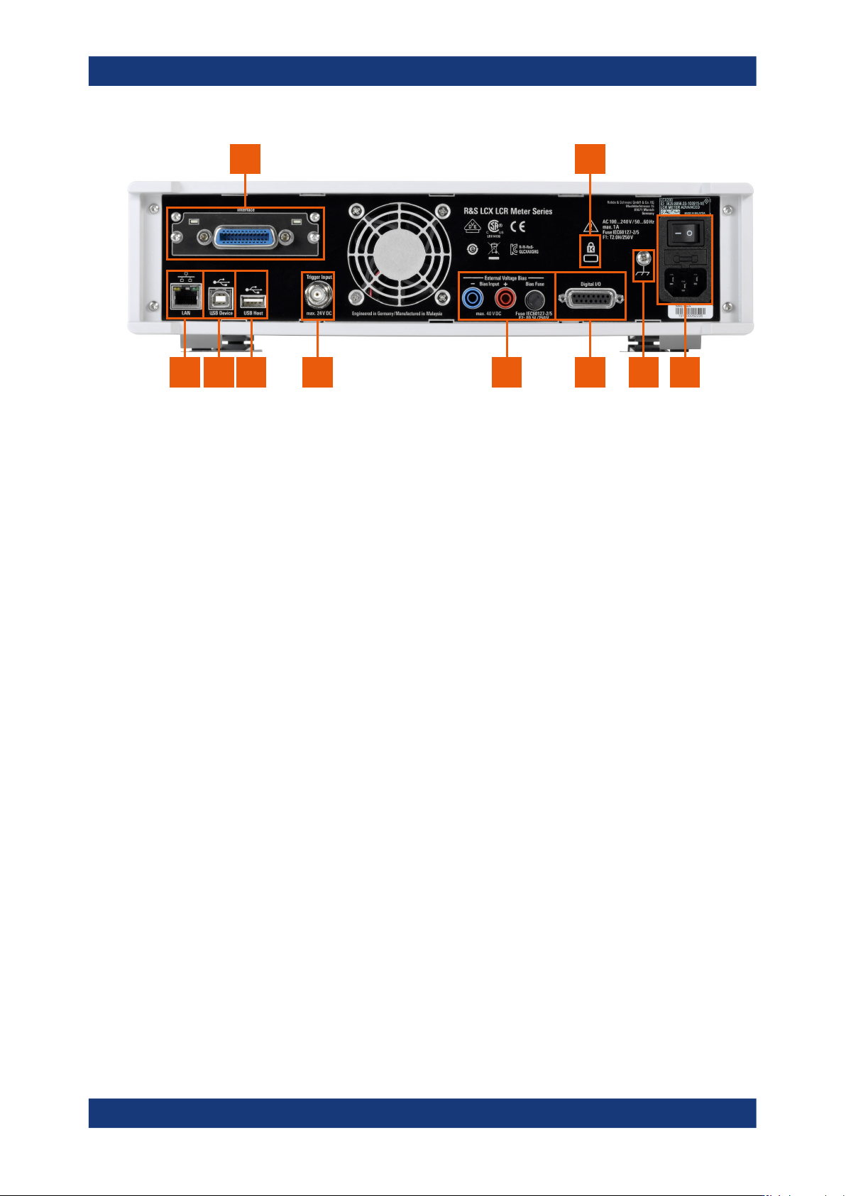
Figure 4-6: R&S
LCX rear panel
1 = IEEE-488 interface, see "IEC 625/IEEE 488" on page 32
2 = Kensington lock, see "Kensington lock" on page 32
3 = AC power connector and power switch, see "AC power supply" on page 32
4 = Ground terminal, see "Ground terminal" on page 33
5 = D-sub connector, see "Digital I/O" on page 33
6 = Bias connectors and fuse holder, see "External Voltage Bias" on page 33, "BIAS Fuse" on page 33
7 = Trigger input connector, see "Trigger Input" on page 33
8 = USB host connector, see "USB A" on page 31
9 = USB device connector, see "USB B" on page 33
10 = Ethernet (LAN) interface connector, see "LAN" on page 33
IEC 625/IEEE 488
Option: R&S NG-B105
General purpose interface bus (GPIB): interface to connect a computer for remote con-
trol of the R&S LCX.
See "Establishing the GPIB remote control connection" on page 168.
Kensington lock
Flat key security slot to prevent the instrument from removal.
The locking system consists of a small, metal-reinforced hole with a metal anchor and
a rubberized metal cable that is secured with a key lock. The loop at the end of the
cable allows you to tie the unit to a fixed object.
AC power supply
Mains power supply with power switch, fuse holder and IEC socket.
●
Mains power switch:
Switch for connecting and disconnecting the internal power supply from the power
source, see Section 4.1.10, "Switching on or off", on page 27.
●
Fuse holder
Socket for the fuse securing the line voltage. Depending on the power supply sys-
tem, the corresponding fuse must be plugged before connecting to power. See
"Connecting to power" on page 23.
●
IEC socket
Instrument tour