LCX_UserManual_en_08_1.pdf - 第89页
Instrument functions R&S ® LCX Series 89 User Manual 1 179.2260.02 ─ 08 c) Select "Open Correction (Spot)" > "Start". The R&S LCX displays a message that prompts you to open the terminals. …
Instrument functions
R&S
®
LCX Series
88User Manual 1179.2260.02 ─ 08
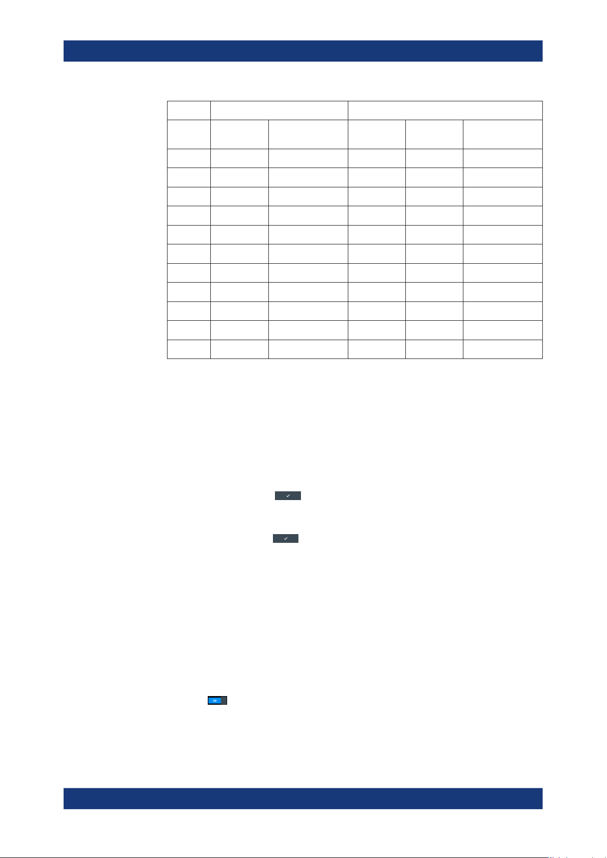
Open correction Short correction
Fre-
quency
High Z 100 Ω High Voltage > 2V Low Z 10 Ω High Z 100 Ω High Voltage > 2V
500 kHz x x x x x
1 MHz x x x x x
2 MHz x
x
3 MHz x
x
4 MHz x
x
5 MHz x
x
6 MHz x
x
7 MHz x
x
8 MHz x
x
9 MHz x
x
10 MHz x
x
The corresponding icon in the measurement status bar turns white, indicating that
compensation is active, see "Measurement status bar" on page 41.
Aligning the instrument on a dedicated working point
To perform a spot correction:
1. To set the working point:
a) Press the [Freq.] key at the front.
b) Enter the test signal frequency, e.g. 10 kHz using the keypad on the screen.
c)
Confirm you setting
.
d) Press the [Level] key.
e) Enter the level, e.g. 1.3 VRMS.
f)
Confirm the setting
.
g) Press the [Range] key.
Note: To achieve most accuracy, we recommend that you perform all spot cor-
rections in the "Auto" measurement range.
h) In the measurement range dialog, select "Auto".
2. Press the [Comp.] key at the front panel.
The "Open/Short/Load Correction" dialog opens.
3. Perform an open spot correction, in this example described for the axial/radial lead
type test fixture (R&S LCX-Z1):
a) Select "Open Correction".
b)
Turn
"Enabled".
Measurement parameters

Instrument functions
R&S
®
LCX Series
89User Manual 1179.2260.02 ─ 08
c) Select "Open Correction (Spot)" > "Start".
The R&S LCX displays a message that prompts you to open the terminals.
Note: If you have selected a measurement range other than "Auto", the
R&S LCX displays a message that prompts you to confirm the range setting.
d) If you have inserted any component, remove it from the slots of the test fixture.
Note: If you are using another test fixture, take care that you set the required
position. For example, Kelvin clamps require the same position as expected for
the measurement, or the spacing between SMD pins must correspond to the
size of the measurement sample.
e) Confirm the message with "Start".
The R&S LCX displays a progress message until the correction is completed.
f) Confirm with "OK".
g)
Return with
to the "Open/Short/Load Correction" dialog.
4. Perform a short spot correction:
a) Select "Short Correction".
b)
Turn "Enabled".
c) Select "Start Short Correction (Spot)".
The R&S LCX displays a message that prompts you to short-circuit the termi-
nals.
d) Short-circuit the contacts, i.e. insert the supplied short circuit plate into the slots
of the test fixture.
e) Confirm the message with "Start".
The R&S LCX displays a progress message until the correction is completed.
The corresponding icon in the measurement status bar turns blue and shows a dot
in the icon. Blue color denotes that spot correction data is enabled, see "Measure-
ment status bar" on page 41. The dot indicates that the correction data applies to
the current working point only.
Note: If you set another frequency, the compensation is invalid and the icon turns
gray. If you change measurement settings, the icon turns yellow, denoting that the
enabled spot correction data applies to a measurement with different settings.
Aligning the instrument using load correction
For executing load correction, the R&S LCX requires a reference value of any compo-
nent to derive the results of the following measurements.
The component can be a resistor or a capacitor with a known impedance. I.e., a com-
ponent that is similar in value and shape to the samples you want to measure, or one
of the series of samples used as the default (standard) value.
A prerequisite is also that you perform the open and short correction before.
1. To run the short and open spot corrections, proceed as described in "Aligning the
instrument on a dedicated working point" on page 88.
2. Select "Load Correction".
3. Set the resistance and the reactance values of the reference component, e.g.:
Measurement parameters

Instrument functions
R&S
®
LCX Series
90User Manual 1179.2260.02 ─ 08
a) Set "Reference Load R" = 10
k
Ω
b) Set "Reference Load X" = 0
Ω
4. Perform a load spot correction:
a) Select "Load Correction".
b)
Turn
"Enabled".
c) Connect the reference component.
d) Select "Start Load Correction (Spot)".
Saving/recalling full correction data
The instrument enables you to save correction data of a full correction for later reuse.
This function requires that you have performed a correction before.
1. To run the open and short correction, proceed as described in "Aligning the instru-
ment on all frequencies" on page 36.
2. Select "Open/Short/Load Correction".
3. Select "Correction Storage".
4. To save the correction data set, select "Save Corrections".
5. Select a slot, e.g. "1".
The R&S LCX saves the correction data set and closes the on-screen editor.
6. To retrieve a correction data set, proceed in the same way with "Restore Correc-
tions".
8.7 Configuration preset
The configuration preset function enables you to assign up to three measurement con-
figurations as favorites to the preset keys. By selecting a favorite, the R&S LCX
changes all predefined parameter settings at once, and thus provides to switch quickly
between different measurement settings and conditions.
About configuration preset
Aspects on the functionality:
●
Included parameters
The configuration preset comprises almost all parameters relevant for a measure-
ment:
– Test signal: frequency and level
– Measurement function: L/C/R/Transformer
– Measurement speed
– Cable length
– DC voltage and low current states
– Open/Short/Load correction states
Configuration preset