LCX_UserManual_en_08_1.pdf - 第26页
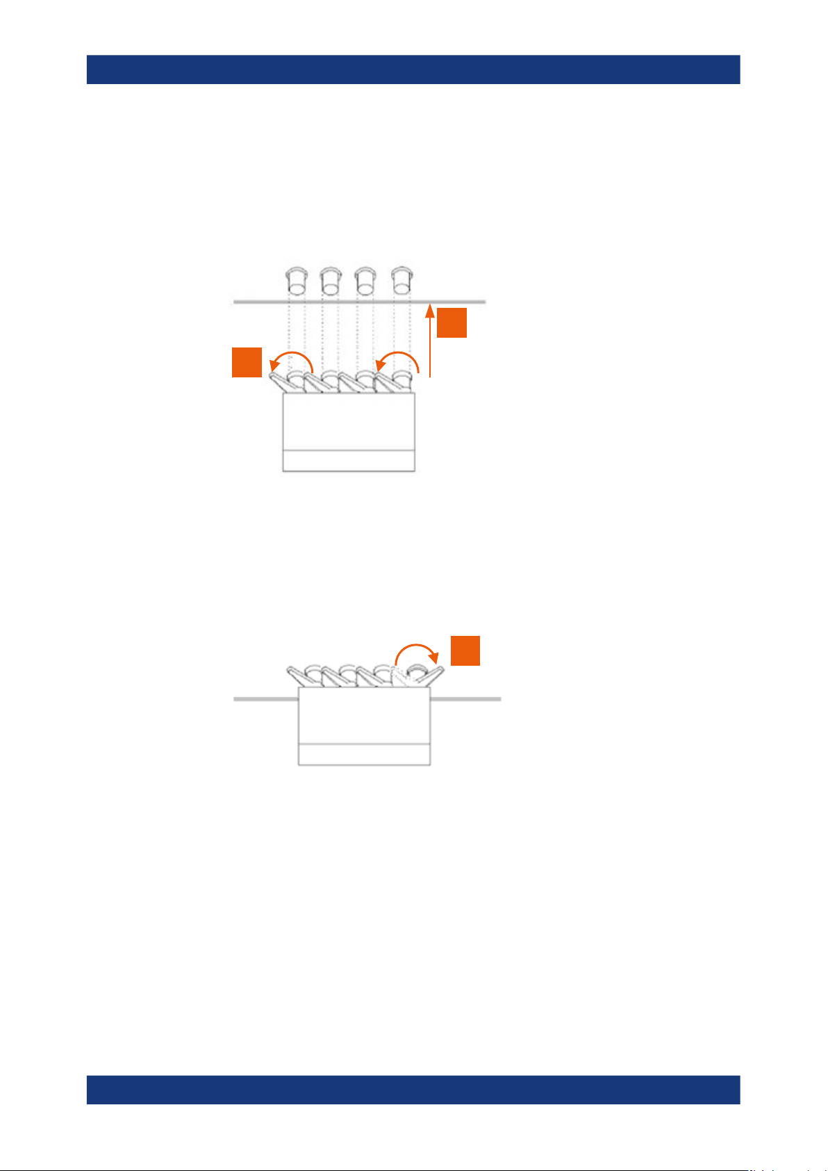
Getting started R&S ® LCX Series 26 User Manual 1 179.2260.02 ─ 08 T urn the levers at the "BNC" connectors of the test fixture to the left to release the lock (1). 1 2 Figure 4-2: Connecting a test fixture…

Getting started
R&S
®
LCX Series
25User Manual 1179.2260.02 ─ 08
4.1.8 Connecting USB devices
The "USB A" connector is at the front panel. You can connect or disconnect all USB
devices from the R&S LCX during operation. But do not remove an external USB mem-
ory stick while the instrument is saving data, since it leads to loss of data.
To connect USB storage devices
USB storage devices, such as memory sticks, allow easy data transfer from or to the
R&S LCX. You can also use them for firmware updates.
► Connect the USB storage device to the "USB A" connector.
If you use the front panel connectors, connect the USB storage device directly,
without connecting cable. Connecting cables can cause electromagnetic radiation
and impair the measurement result.
To connect USB devices with an external power supply
It is also possible to use a USB device with an external power supply.
1.
NOTICE! Connected devices with external power supply can feed back current into
the 5 V power supply of the USB interface and thus damage the R&S LCX.
Make sure that there is no connection between the positive pole of the power sup-
ply and the +5 V power pin of the USB interface (VBUS).
2. Connect the USB storage device to the "USB A" connector at the front panel.
4.1.9 Connecting a test fixture
The R&S LCX enables you to measure passive components like capacitors, coils,
resistors, transformers. To measure such components requires the use of suitable
measurement adapters, in this context considered as test fixtures.
For information on the test fixtures available for the R&S LCX, see Measurement Set-
ups > About Test Fixtures.
The test fixtures are connected firmly to the four BNC connectors H POT (high poten-
tial), H CUR (high current), L POT low potential) and L CUR (low current) at the front
panel.
The following instructions describe the mechanical connection of the adapter only.
Before starting a measurement, consider the prerequisites and steps to be performed
before as described in Section 4.3, "Trying out the instrument", on page 34.
Connecting a test fixture to the instrument
To connect a 4-terminal test fixture to the R&S LCX:
1.
NOTICE! Check all terminals to make sure that they are not damaged.
NOTICE! Before connecting, discharge all components. Externally supplied voltage
can damage the BNC connectors of the R&S LCX.
Preparing for use
Getting started
R&S
®
LCX Series
26User Manual 1179.2260.02 ─ 08
Turn the levers at the "BNC" connectors of the test fixture to the left to release the
lock (1).
1
2
Figure 4-2: Connecting a test fixture
2. Carefully plug the test fixture to the four "BNC" measurement connectors of the
R&S LCX (2).
3. Turn all levers to the right to tighten the connection (3).
3
Figure 4-3: Fastening the test fixture
The mechanical test setup is ready for operation.
Connecting a test fixture with the BNC-to-BNC extension
If you are using the BNC-to-BNC extension (option R&S LCX-Z11), you can connect all
devices as described in Connecting a test fixture to the instrument. We recommend
that you keep the order as follows:
1. Connect the BNC-to-BNC to the R&S LCX.
Proceed as described in step 1.
2. Connect the test fixture to the extension.
Preparing for use

Getting started
R&S
®
LCX Series
27User Manual 1179.2260.02 ─ 08
4.1.10 Switching on or off
Switching on the product
The product is off but connected to power.
1. Set the switch on the power supply to position [I].
The power supply switch connector is on the rear panel.
The R&S LCX starts, and the front panel keys light up briefly.
2. Press the power key for a second.
The power is on the front panel.
The instrument checks the system, boots the operating system, and then starts the
R&S LCX firmware.
The power lights green.
When starting for the first time, the R&S LCX starts with the default settings. When
restarting the instrument, the settings depend on the instrument configuration
before shut-down.
Shutting down the product
► Press the power key.
All current settings are saved and the operating system shuts down.
The power changes to gray (off).
To disconnect from power
The product is in the standby state.
1.
NOTICE! Risk of data loss. If you disconnect the product from power when it is in
the ready state, you can lose settings and data. Shut it down first.
Set the switch on the power supply to position [0].
2. Disconnect the product from the power source.
4.2 Instrument tour
The following topics help you to get familiar with the instrument and perform the first
steps:
●
Front panel tour
●
Rear panel tour
The sections explain the controls and connections at the front and back of the
R&S LCX. For specifications of the interfaces, see the specifications document.
The meanings of the labels on the R&S LCX are described in Section 1.2, "Labels on
the R&S LCX", on page 12.
Instrument tour