YSi-SP_Ope_E.pdf - 第101页
2-64 2 Operation 2. Correction is made to the fiducial mark data having been entered. T he image of the fiducial mark is display ed. T he currently entered coordinates of the fiducial mark are shown at the upper right of…
2-63
2
Operation
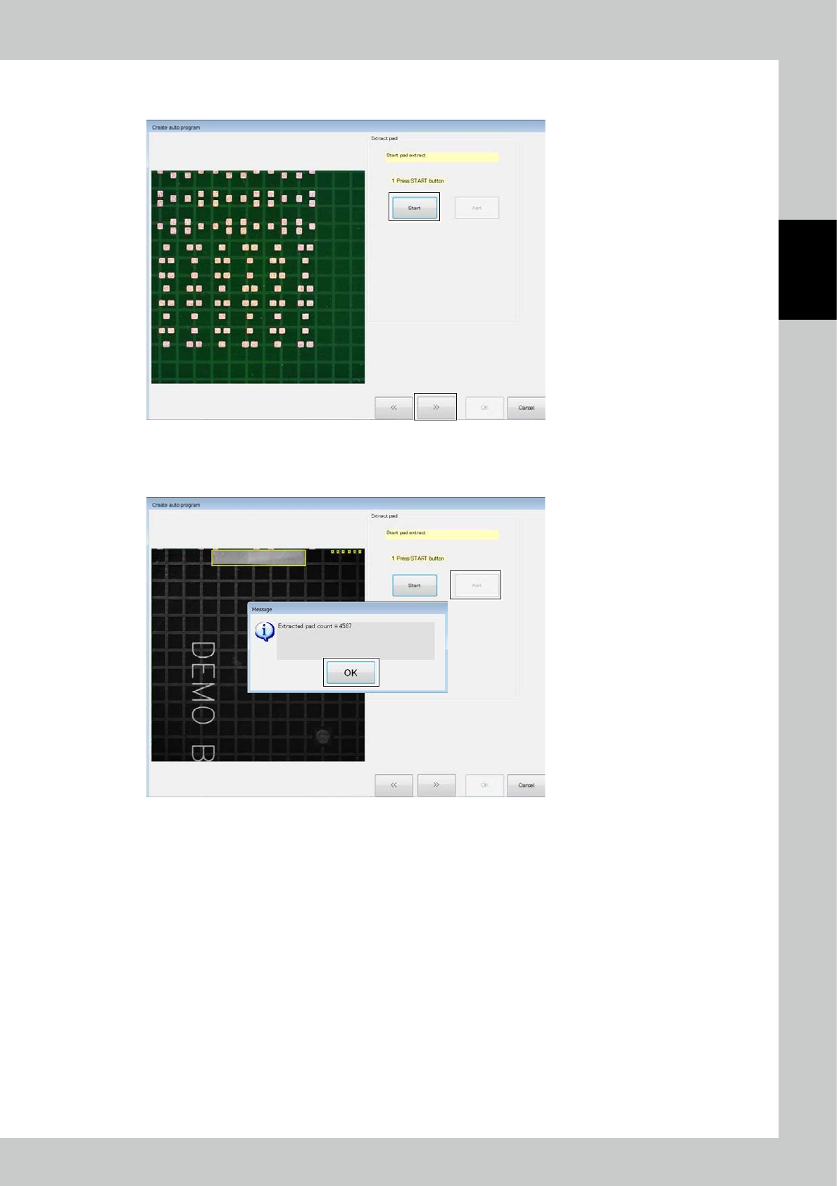
Click on the [Start] button to start to extract pads.
After pad extraction is finished, click on the [>>] button.
24287-KMN-00
To interrupt pad extraction in the middle, click on the [Abrt] button.
The above window opens with the number of extracted pads. Click on the [OK] button.
24288-KMN-00
2-64
2
Operation
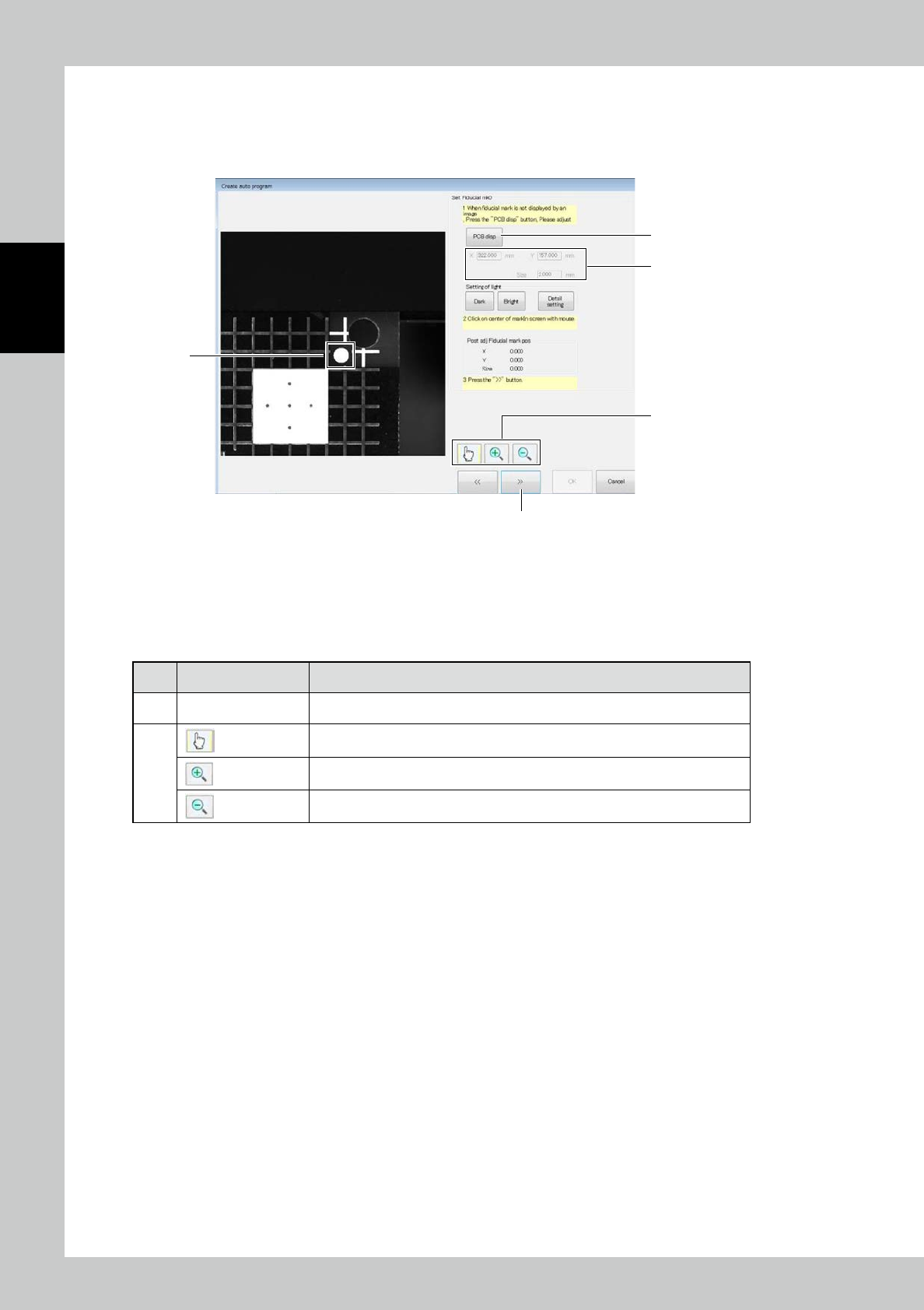
2. Correction is made to the fiducial mark data having been entered.
The image of the fiducial mark is displayed. The currently entered coordinates of the fiducial mark are shown at the
upper right of the screen.
Use the [Bright] or [Dark] button to adjust the brightness of the image.
1
4
5
2
3
24290-KMN-00
1. Click on the approximate center of the fiducial mark.
2. Coordinates of the fiducial mark are corrected and the position of the fiducial mark after correction is displayed.
3. After correction is finished, click on the [>>] button.
■
Description of buttons
No Name Description of displayed item and functions
4 [PCB Disp] button The PCB image and the field of view image are switched over.
5
Start the edit mode.
Start the zoom-in mode.
Start the zoom-out mode.
2-65
2
Operation
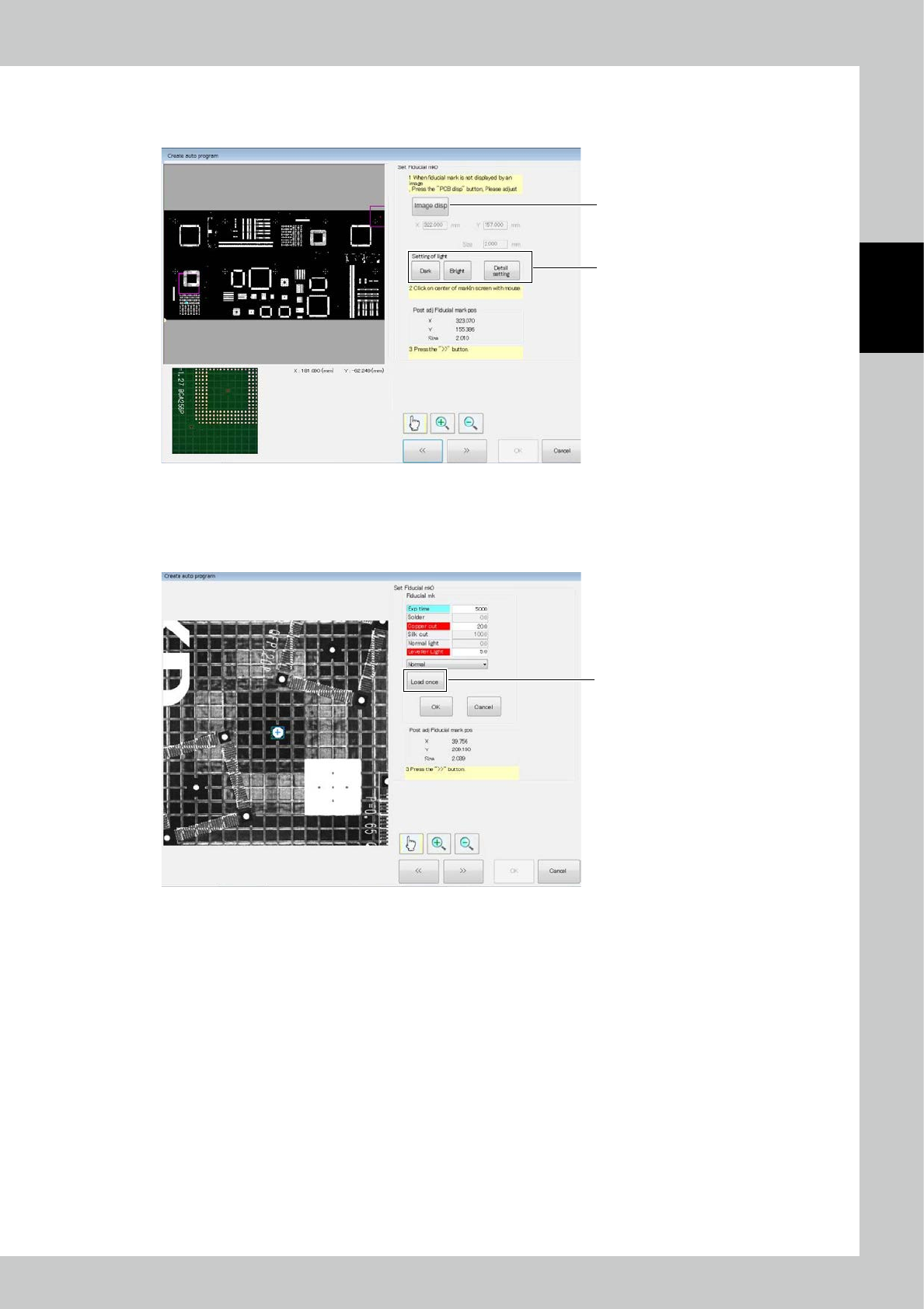
6. Press the [Image disp] button to change the position of the field of view.
Click on the PCB image. The field of view image is displayed below.
Adjust the position so that the fiducial mark is in the field of view.
6
7
24291-KMN-00
7. Press the [Detail setting] button to give detail settings for extracting the fiducial mark.
If the center is not successfully detected though the center of the mark is designated, change the extraction setting so
that the center is detected.
Press the [Load once] button to preview the image obtained with the new light intensity.
[Load once] button
24292-KMN-00