YSi-SP_Ope_E.pdf - 第125页
2-88 2 Operation 3. T ouch the [>>] button. The screen shown belo w is display ed. 4 5 242C2-KMN-00 4. Enter settings of pattern and resist extr action. Item Description Adj light Specify the height measurement str…
2-87
2
Operation
1. Setting check
1. Touch the [Setting] button to display the screen shown below.
2
3
242C1-KMN-00
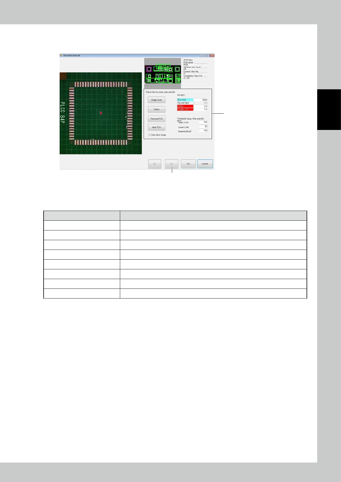
2. Cut the silk, electrode and solder.
■
Check the Cut area, pole and silk
Item Description
Adj light Specify the electrode and the 2D image light source for silk cutting.
Upper limit Adjust the upper limit threshold for extracting the electrode and silk cut sections.
Lower limit Adjust the lower limit threshold for extracting the electrode and silk cut sections.
Expansion [um] The cut section is expanded.
Single Grab Take the 2D image again.
Check Extract the electrode and silk cut sections from the taken 2D image and show them in purple.
Previous FOV/Next FOV Move the field of view for checking the electrode and silk cut sections.
Disp Mono Image Show the 2D image used for judgment, on the left side of the screen.
2-88
2
Operation
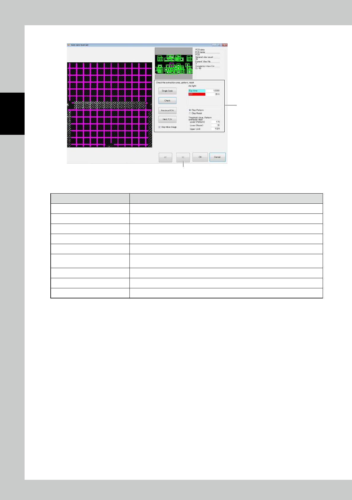
3. Touch the [>>] button. The screen shown below is displayed.
4
5
242C2-KMN-00
4. Enter settings of pattern and resist extraction.
Item Description
Adj light Specify the height measurement stripe light source for pattern and resist extraction.
Upper Limit
(
Contrast) Adjust the upper limit threshold for extracting the pattern and resist.
Lower (Pattern) Adjust the lower limit threshold for pattern extraction.
Lower (Resist) Adjust the lower limit threshold for resist extraction.
Single Grab Take the height measurement stripe image again.
Check
Extract the pattern and resist from the taken stripe image for height measurement and show
them in pink and orange.
Previous FOV/Next FOV Move the field of view for checking the pattern and resist extraction.
Disp Pattern/Disp Resist Select the image to be displayed when the confirm button is clicked on.
Disp Mono Image Show the stripe image used for judgment, on the left side of the screen.
2-89
2
Operation
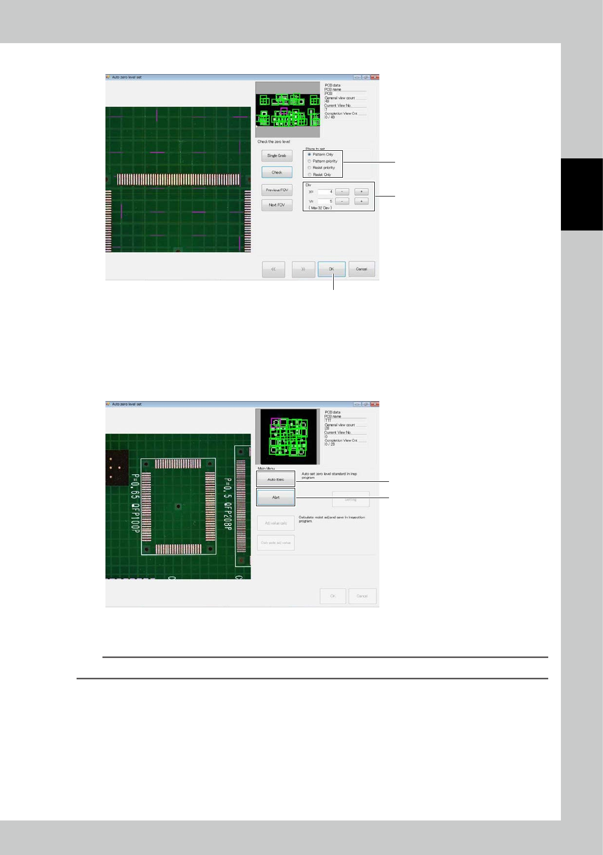
5. Touch the [>>] button.
8
7
6
242C3-KMN-00
6. Select corresponding zero level installation among “Pattern only,” “Pattern priority,” “Resist priority” and “Resist only.”
Click on the Confirm button to arrange the zero level according to the current setting.
7. Determine the division where the zero level is to be placed. Register one zero level in each division area.
8. After data entry are finished, touch the [OK] button.
2. Automatic execution
2
1
242C4-KMN-00
1. After checking the settings described above, click on the [Auto Exec] button to arrange the zero level in all fields of
view. After the marks are arranged, a message is displayed. Click on the [OK] button to finish.
TIP
You can click on the [Abrt] button 2 during automatic execution to cancel automatic execution.