YSi-SP_Ope_E.pdf - 第130页
2-93 2 Operation 5. Maintenance Method 5.1 Precautions • Warm up for 10 minutes to stabilize the measuring instrument. • Slowly turn the main circuit breaker or the key on or off. In particular , leave at least three sec…
2-92
2
Operation
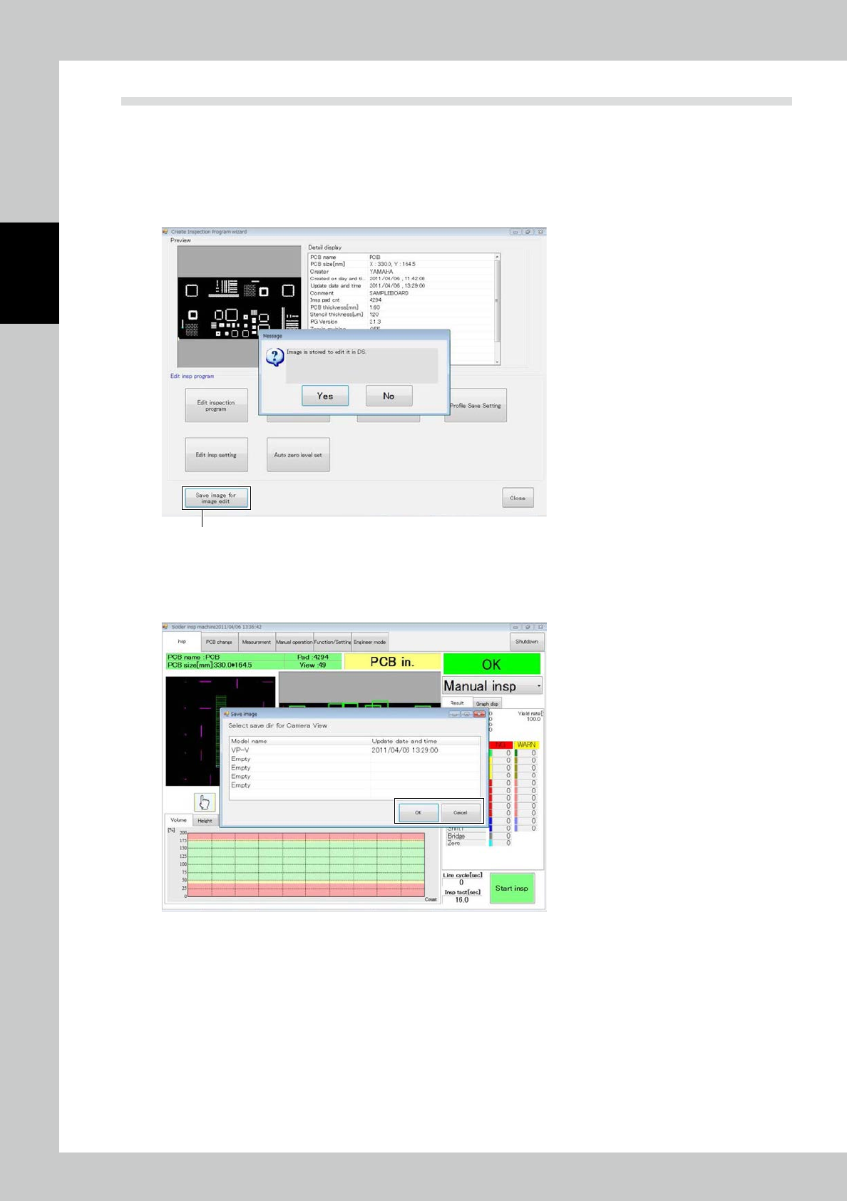
4.5 Saving the Camera Image
Images taken by the camera of the inspection machine are saved at the data station so that the fiducial mark is
edited and zero level is set at the data station.
The work conducted at the inspection machine moves to the desktop, increasing the availability of the line.
1
Click on the [Save image for image edit] button.
If the data station is not connected, the image is stored in the PC inside the inspection machine.
[Save image for image edit] button
242C7-KMN-00
2
Select the destination of saving and click on [OK].
Click on [Cancel] to cancel saving.
242C8-KMN-00
2-93
2
Operation
5. Maintenance Method
5.1 Precautions
• Warm up for 10 minutes to stabilize the measuring instrument.
• Slowly turn the main circuit breaker or the key on or off. In particular, leave at least three seconds between shutoff and
power-on. Otherwise the CPU may not start correctly.
• Periodically back inspection programs and other data.
• Do not open the front door or reach inside during operation.
• When finishing the operation, never fail to touch the shut down button on the main menu to finish the operation
system, and then turn the operation power off. If the power is turned off without finishing the termination process, the
system may be damaged.
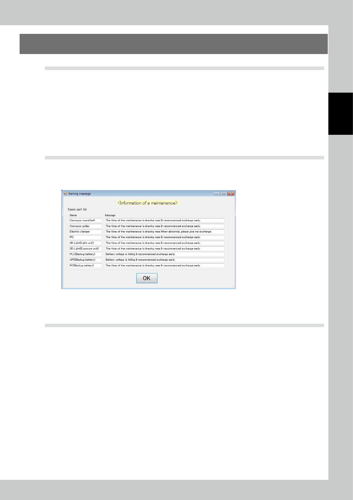
5.2 Maintenance Parts
Warning message shall be announced when replace timing for the parts, mentioned on the spare parts list of
the operation manual mechanical volume, is coming. The announcement shall occur when the machine is
logged in.
242C9-KMN-00
The details of the maintenance parts should be referred to “3.6.12 Maintenance disp” or the spare parts list on
the operation manual mechanical volume.
5.3 Troubleshooting
An emergency stop state is caused when the equipment is stopped. The emergency stop state occurs in the
following cases.
1. There is trouble in equipment (programmable logic controller).
2. There is physical trouble during travel of the XY table.
※ Recovery from emergency stop
1. Remove the cause of the emergency stop. If the emergency stop switch has been pressed, turn the switch to reset it.
2. Select the standalone inspection temporarily if the automatic inspection mode has been selected.
The equipment recovers in the above operation. The equipment is in the following state according to the mode of the
equipment having been selected before the emergency stop.
• Automatic inspection mode: State waiting for startup
• Standalone inspection mode: State before emergency stop
2-94
2
Operation
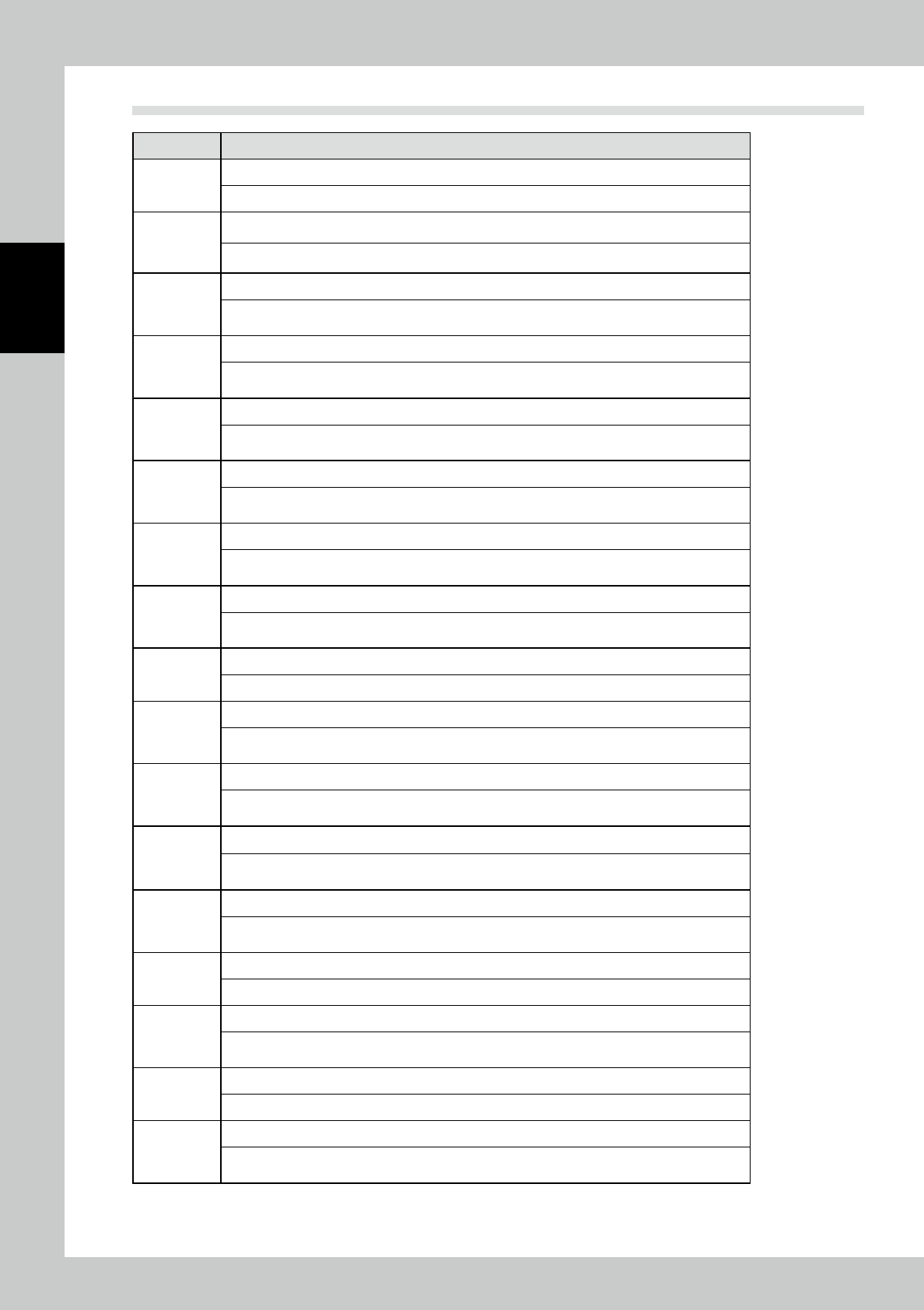
5.4 Error Code List
I/O Comment
2000
Emergency stop
An emergency stop switch (PB2300) was pressed.
2001
Safety cover open error
The safety cover (LS2308) is open. Close the safety cover.
2002
Loading conveyor opening fault
Thve safety cover of the loading conveyor opened during conveyor width adjustment.
Close the safety cover.
2003
Unloading conveyor opening fault
The safety cover of the loading conveyor opened during conveyor width adjustment.
Close the safety cover.
2004
X-axis servo driver error
An alarm signal is issued from the X-axis servo driver (SD200). Remove the error while referring
to the servo driver instruction manual.
2005
X-axis overrun (+)
The overrun sensor for the positive direction of the X-axis table is turned on. Push back toward
the inside of the machine manually.
2006
X-axis overrun (-)
The overrun sensor for the negative direction of the X-axis table is turned on. Push back toward
the inside of the machine manually.
2007
X-axis home position error
Home position determination in the X-axis is not finished in the predetermined time. Press the
RESET switch to reset.
2008
X-axis positioning error
The X-axis action is not finished in the predetermined time. Press the RESET switch to reset.
2009
Y-axis servo driver error
An alarm signal is issued from the X-axis servo driver (SD300). Remove the error while referring
to the servo driver instruction manual.
200A
Y-axis overrun (+)
The overrun sensor for the positive direction of the Y-axis table is turned on. Push back toward
the inside of the machine manually.
200B
Y-axis overrun (-)
The overrun sensor for the negative direction of the Y-axis table is turned on. Push back toward
the inside of the machine manually.
200C
Y-axis home position error
Home position determination in the Y-axis is not finished in the predetermined time. Press the
RESET switch to reset.
200D
Y-axis positioning error
The Y-axis action is not finished in the predetermined time. Press the RESET switch to reset.
200E
Z-axis home position error
Home position determination in the Z-axis is not finished in the predetermined time. Press the
RESET switch to reset.
200F
Z-axis positioning error
The Z-axis action is not finished in the predetermined time. Press the RESET switch to reset.
2011
Inspection conveyor width adjustment (narrow) overrun
The action range detection sensor (PHRX0001) (normal upon active state) of the inspection
conveyor width adjustment axis pulse motor is turned off. Press the RESET switch to reset.