YSi-SP_Ope_E.pdf - 第74页
2-37 2 Operation 3.6 Function/Setting Items displa yed on the function/setting screen and functions are described. Y ou can configure the main body of the inspection machine on this screen. T he setting screen includes i…
2-36
2
Operation
4
5
6
1
2
3
7 8 9
10
11
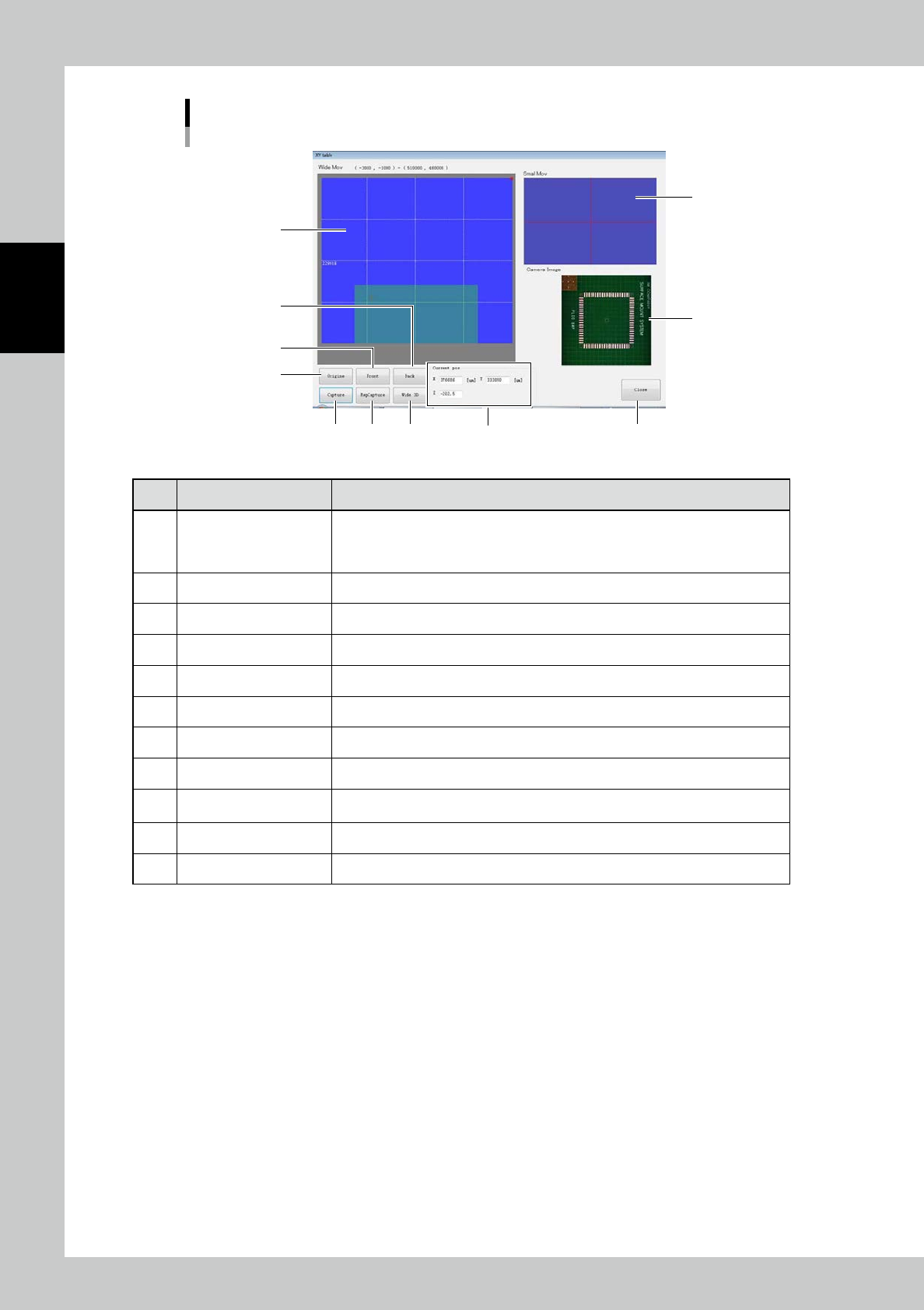
XY table screen
24244-KMN-00
No Name Description of displayed item and functions
1 Wide area travel screen
The XY table traveling area is indicated with a blue screen. Touch the screen to
move the XY table to a desired position. The position of the XY table is indicated
with a pink cross. The bottom side of the screen corresponds to the nearer side of
the inspection machine.
2 Detail travel screen The machine moves similarly to 1); the XY table travels finely.
3 Camera image The camera image is displayed.
4 [Origin] button The XY table travels to the home position of the inspection machine.
5 [Front] button The XY table travels so that the camera unit is in the nearest position.
6 [Back] button The XY table travels so that the camera unit is in the farest position.
7 [Single Grab] button The image is acquired once.
8 [Continuous Grab] button Images are acquired continuously.
9 [Wide 3D] button
The wide area measurement screen opens. (Refer to "3.4.2 Wide Area Measurement
Screen".)
10 Current pos The X and Y coordinates are displayed. Enter desired values to move the XY table.
11 [Close] button Exit to return to the manual operation screen.
2-37
2
Operation
3.6 Function/Setting
Items displayed on the function/setting screen and functions are described. You can configure the main body of
the inspection machine on this screen.
The setting screen includes insp setting relation and display relation.
4 5
6
1
2
3
7
8
9
10 11
12
13
24245-KMN-00
■
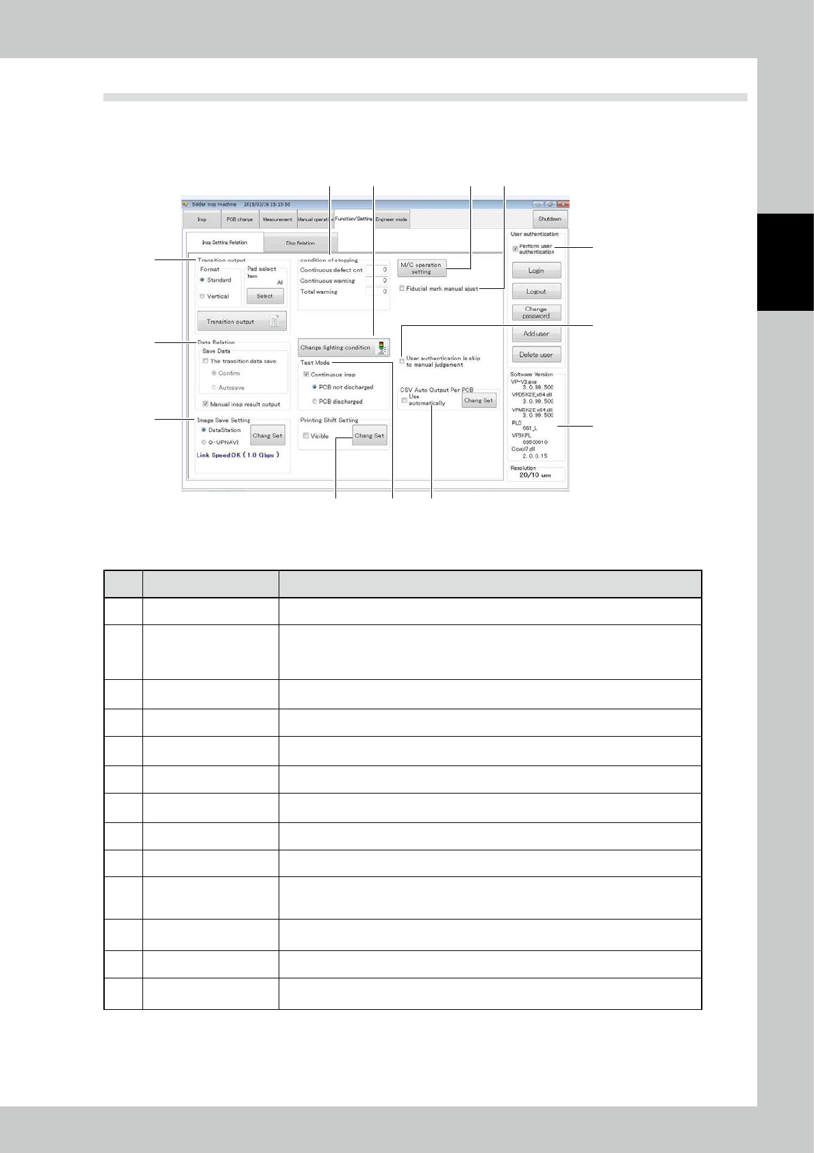
Insp Setting Relation
No Name Description of displayed item and functions
1 Transition output The inspection results are converted into a CSV file.
2 Data Relation
[The tradition data save] Save the inspection data upon PCB change.
[Confirm] Show a confirmation message when the data is stored.
[Autosave] Save the data without a message.
[Manual insp result output] Output the data even during inspection in the manual mode.
3 Image Save Setting
Enter settings for storing the measured image to an external PC.
(Refer to "3.6.2 Image Save Setting".)
4 Condition of stopping Enter conditions for stopping the machine during automatic operation.
5 Change Lighting condition
Change conditions for lighting the tower light of the equipment. (Refer to "3.6.4 Tower
Light Setting".)
6 Test Mode Mode for testing the PCB during automatic operation. The PCB is not discharged.
7 Print Gap Setting
Enter settings for displaying the result of print gap on the inspection screen.
(Refer to "3.6.6 Print Gap Setting".)
8 User authentication The "operator authentication screen" is displayed. (Refer to "3.6.3 User Authentication".)
9 Software version The version of the inspection machine control system is displayed.
10 M/C operation Setting
Change the loading and unloading speed of the conveyor of the main body.
Also, change the setting for obtaining the buffer when operating. (Refer to"3.6.7 M/C
operation setting".)
11
Fiducial mark manual
adjust
Manual registration can be made upon a mark recognition error. (Refer to "3.6.8 Fiducial
mark manual adjust")
12 Skip When manual inspection,skipping a user authentication.
13 CSV Output
After inspection every time has ended,data is output.(Refer to "3.6.13 CSV Auto Output
Per PCB")
2-38
2
Operation
■
Stopping conditions setting
1. Continuous defect cnt
The equipment is stopped if the continuous PCB defect count has reached the setting.
(Example) Enter "1" to check details of the defect on the screen of the equipment.
2. Continuous warning
The equipment is stopped if the continuous PCB warning count has reached the setting.
3. Total warning
The equipment is stopped if the cumulative number of PCB warnings has reached the setting.
6 7
1
2
3
4
5
8
9
1110
24246-KMN-00
■
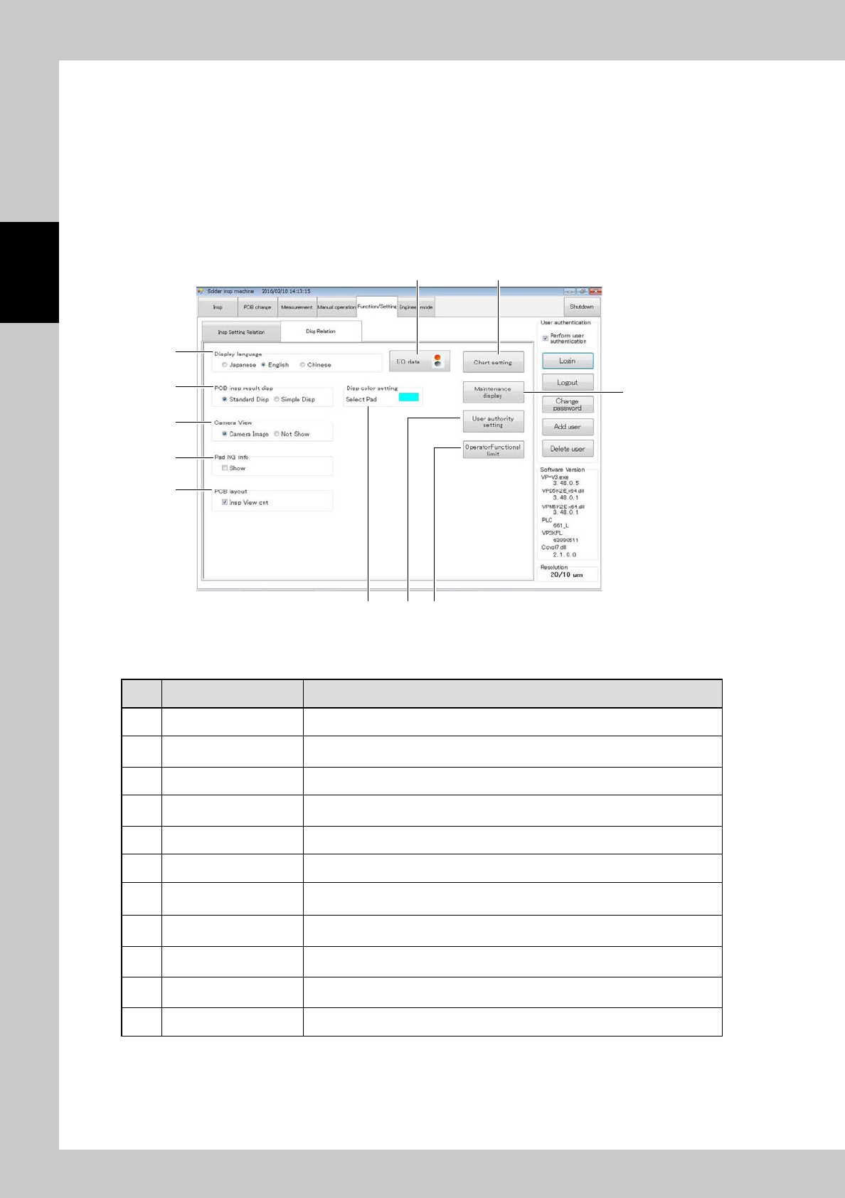
Disp Relation
No Name Description of displayed item and functions
1 Display language The language displayed on all screens is switched.
2 PCB insp result disp
The display result of the main tab and measurement tab can be switched between
standard display and simple display. (Refer to "3.6.11 PCB insp result disp".)
3 Camera View Enter the display setting of the view field image in inspection.
4 Pad NG info
The NG info display of the individual pad can be switched. (Refer to "3.6.10 Pad NG
info".)
5 PCB layout Setting up for the display of PCB layout screen.
6 I/O data Show the "I/O Data Display screen." (Refer to "3.6.1 I/O Data Display Screen".)
7 Chart setting
Enter the graph display setting on the measurement tab. (Refer to "3.6.5 Chart
Setting".)
8 Maintenance display
Setting up for announce display and coming replace timing.
(Refer to "3.6.12 Maintenance display".)
9 User authority setting
The menu display switching setting can be entered for each log-in user.
(Refer to "3.6.9 User authority setting".)
10 Select Pad Color
You can change the display color of the currently selected to have pad. Opens the
display color setting screen by clicking the display of color.
11 OperatorFunctional limit You can limit some of the functionality that can be used in the Operator privileges.