YSi-SP_Ope_E.pdf - 第120页
2-83 2 Operation 4.2.4 Field of View Editing 1 2 4 3 242B7-KMN-00 1. [View pos] button Change the field of view position. If a zero level mov es out of the field of view when the field of view position is changed, a conf…
2-82
2
Operation
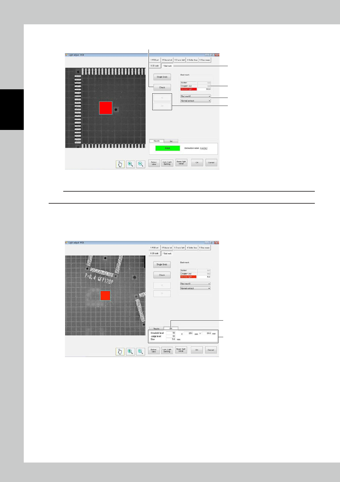
8. Bad Mark
4
1
3
5
2
242B5-KMN-00
1. Touch the [Bad mark] tab.
TIP
The bad mark tab is displayed only if a bad mark is registered in the inspection program.
2. Select the light source to be used and adjust the light intensity.
3. When necessary, select Normal extract or Rev/Extr.
4. Touch [<<] or [>>] to select the bad mark to be checked.
5. Touch
[
Check] to show results.
6
7
242B6-KMN-00
6. To adjust the bad mark position or the like, touch the Set tab.
7. Adjust the
[
threshold level], [Judge level], [Size] and coordinates so that the bad mark is extracted correctly.
2-83
2
Operation
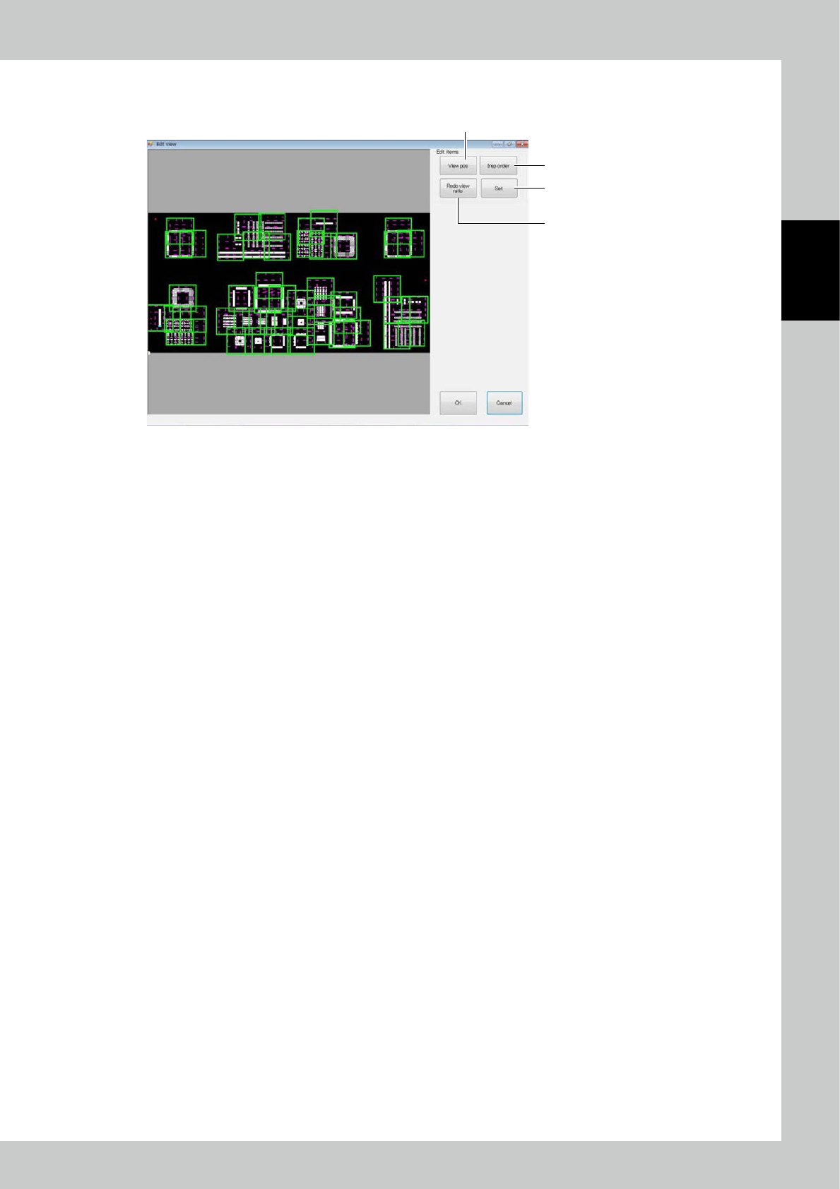
4.2.4 Field of View Editing
1
2
4
3
242B7-KMN-00
1. [View pos] button
Change the field of view position. If a zero level moves out of the field of view when the field of view position is
changed, a confirmation message is displayed.
2. [Insp order] button
The inspection order (moving path of the camera of the inspection machine) of the field of view is changed.
3. [Redo view ratio] button
All fields of view are automatically divided again.
4. [Set] button
The effective range of the field of view is changed.
2-84
2
Operation
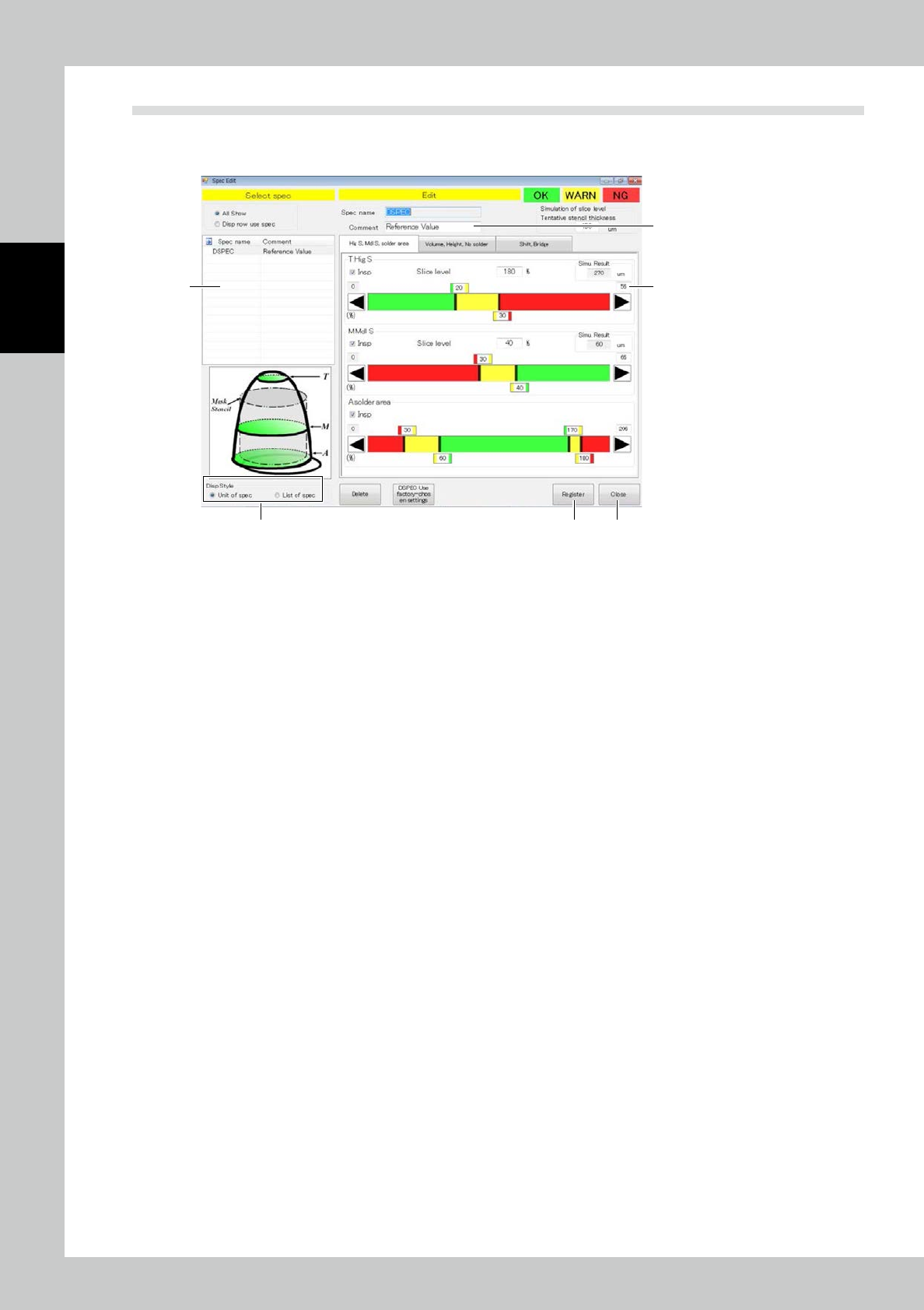
4.3 Spec Data Editing
Edit the spec data.
Touch spec data [Edit] button on the engineer mode screen to display the figure shown below.
1
2
3
4 5
6
242B8-KMN-00
1. Select the spec data to be edited.
2. Enter a comment if you need.
3. According to each inspection item, change the inspection reference value. Touch the upper tab to change over
inspection items.
Inspection is made for inspection items marked with a check mark in the inspection check box. Reset the check box of
unnecessary inspection items for efficient inspection.
4. After spec data is edited, touch the [Register] button.
5. After editing is finished, touch the [Exit] button.
Drag the graph color border or touch the desired arrow button to adjust. The graph color indicates OK (green), WARN
(yellow) or NG (red). Enter the slicing height to the mask thickness in percent directly. For value entry method, refer to
Appendix 2 of the Data Station Volume.