YSi-SP_Ope_E.pdf - 第124页
2-87 2 Operation 1. Setting check 1. T ouch the [Setting] button to display the screen sho wn below . 2 3 242C1-KMN-00 2. Cut the silk, electrode and solder . ■ Check the Cut area, pole and silk Item Description Adj ligh…
2-86
2
Operation
4.4 Automatic Zero Level Setting
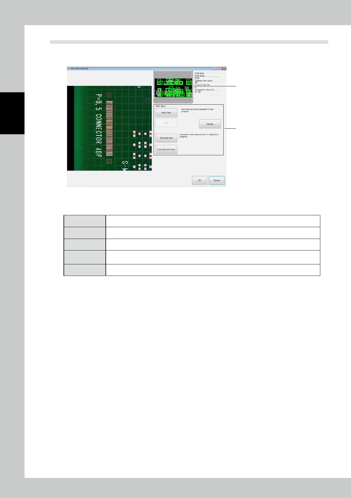
Touch the PCB data [Auto zero level setting] button on the engineer mode screen. The screen shown below is
displayed.
2
1
242C0-KMN-00
1. Touch the frame of the field of view to jump to the field of view.
2. "Automatic zero level setting" includes the following menus.
[Auto Exec] The zero level is arranged in all fields of view according to the current extraction setting.
[Adj value calc] The offset of the resist is manually calculated and saved in the inspection program.
[Abrt] Automatic execution is canceled.
[Setting]
Check the settings such as the electrode, silk cut and pattern and resist extraction. [Calc pole adj value]
Teaching proceeds with a real PCB so that the solder height above the electrode face is measured.
[Exit] Exit from the automatic zero level setting procedure to return to the engineer mode tab screen.
2-87
2
Operation
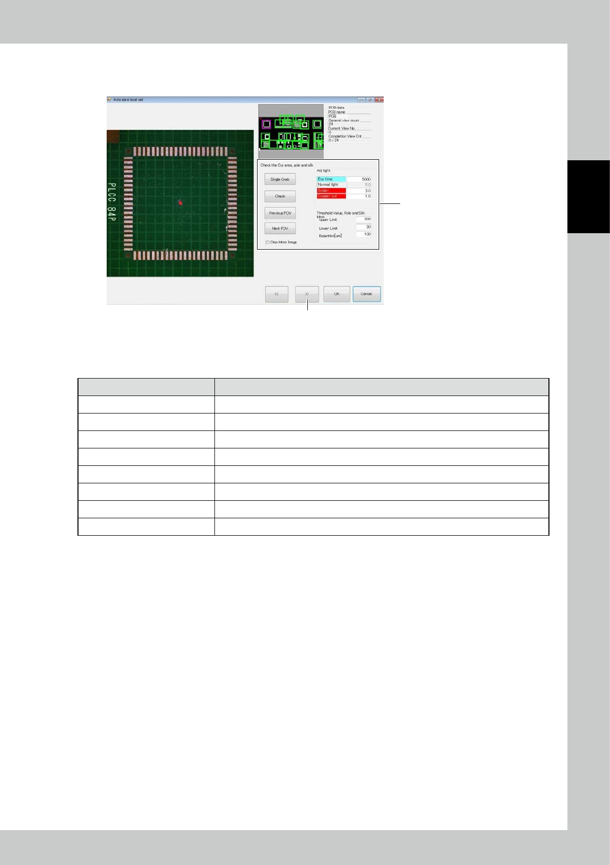
1. Setting check
1. Touch the [Setting] button to display the screen shown below.
2
3
242C1-KMN-00
2. Cut the silk, electrode and solder.
■
Check the Cut area, pole and silk
Item Description
Adj light Specify the electrode and the 2D image light source for silk cutting.
Upper limit Adjust the upper limit threshold for extracting the electrode and silk cut sections.
Lower limit Adjust the lower limit threshold for extracting the electrode and silk cut sections.
Expansion [um] The cut section is expanded.
Single Grab Take the 2D image again.
Check Extract the electrode and silk cut sections from the taken 2D image and show them in purple.
Previous FOV/Next FOV Move the field of view for checking the electrode and silk cut sections.
Disp Mono Image Show the 2D image used for judgment, on the left side of the screen.
2-88
2
Operation
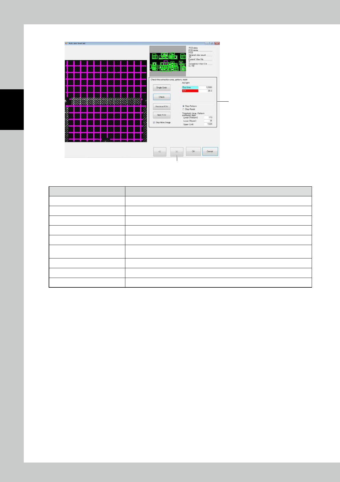
3. Touch the [>>] button. The screen shown below is displayed.
4
5
242C2-KMN-00
4. Enter settings of pattern and resist extraction.
Item Description
Adj light Specify the height measurement stripe light source for pattern and resist extraction.
Upper Limit
(
Contrast) Adjust the upper limit threshold for extracting the pattern and resist.
Lower (Pattern) Adjust the lower limit threshold for pattern extraction.
Lower (Resist) Adjust the lower limit threshold for resist extraction.
Single Grab Take the height measurement stripe image again.
Check
Extract the pattern and resist from the taken stripe image for height measurement and show
them in pink and orange.
Previous FOV/Next FOV Move the field of view for checking the pattern and resist extraction.
Disp Pattern/Disp Resist Select the image to be displayed when the confirm button is clicked on.
Disp Mono Image Show the stripe image used for judgment, on the left side of the screen.