YSi-SP_Ope_E.pdf - 第26页
1-10 1 Over view and maintenance of machine 5. T emporar y measure for PLC/UPS failure This section describes the temporar y measure for PLC/UPS failure. 5.1 Pass Mode of PLC In this machine, a reserv e HDD (Hard disk dr…
1-9
1
Overview and maintenance of machine
4.4 Work size which can be inspected by this machine
■
Work size
Outline (L * W) 50 * 50 to 510 * 460 mm
Weight (MAX) 3.0 kg or less
Board thickness 0.3 to 5.0 mm
4.5 Conditions of work shape
■
Conditions of work shape
Warp of the work
Short
interval
0.3/40 mm or less
Fluctuation
of the entire
interval
±5.0 mm or less
Height of cream solder (MAX)
400 μm or less (Resolution: at 25 um/12.5 um)
300 μm or less (Resolution: at 20 um/10 um)
300 μm or less ((Resolution: at 15 um/7.5 um)
Material and
color of board
Material of
substrate
Glass epoxy, paper phenol, polyimide film base
*Consult with CKD for alumina (ceramic) substrate.
Solder resist
color
Solder resist color shall not be dark color like black.
Consult with CKD for light color.
4.6 Operating environment
■
Operating environment
Room temperature 25 °C to 35 °C (68 °F to 95 °F)
Humidity 50% to 70% (without condensation)
Altitude Average altitude 1000 m or less
Overvoltage section III
Pollution level 3
4.7 Noise value
65dB (A)
Operating Condition : Full load Measuring Method : According to clause 1. 7. 4. 2 of Machinery Directive
2006/42/EC
4.8 Transportation, storage environment
By design or by taking proper preventive measure, electrical equipment can withstand the influence of
temperatures for the transportation and storage temperatures from -25 °C to + 55 °C (-13 °F to 131 °F).
Appropriate measures must be taken to protect the equipment from damages by humidity, vibration, and
impact.
4.9 Rules for design reference
Machinery Directive:
EN ISO12100, EN ISO13849, EN 60204-1, EN ISO13857 etc
1-10
1
Overview and maintenance of machine
5. Temporary measure for PLC/UPS failure
This section describes the temporary measure for PLC/UPS failure.
5.1 Pass Mode of PLC
In this machine, a reserve HDD (Hard disk drive) and UPS (Uninterruptible power source) are equipped as
standard, and a prompt restoration is possible in case of momentary power outage and HDD failure.
However, in case of personal computer failure, it is possible to continue pass transfer (PASS mode) by PLC
(programmable logic controller) for substrate transfer control alone.
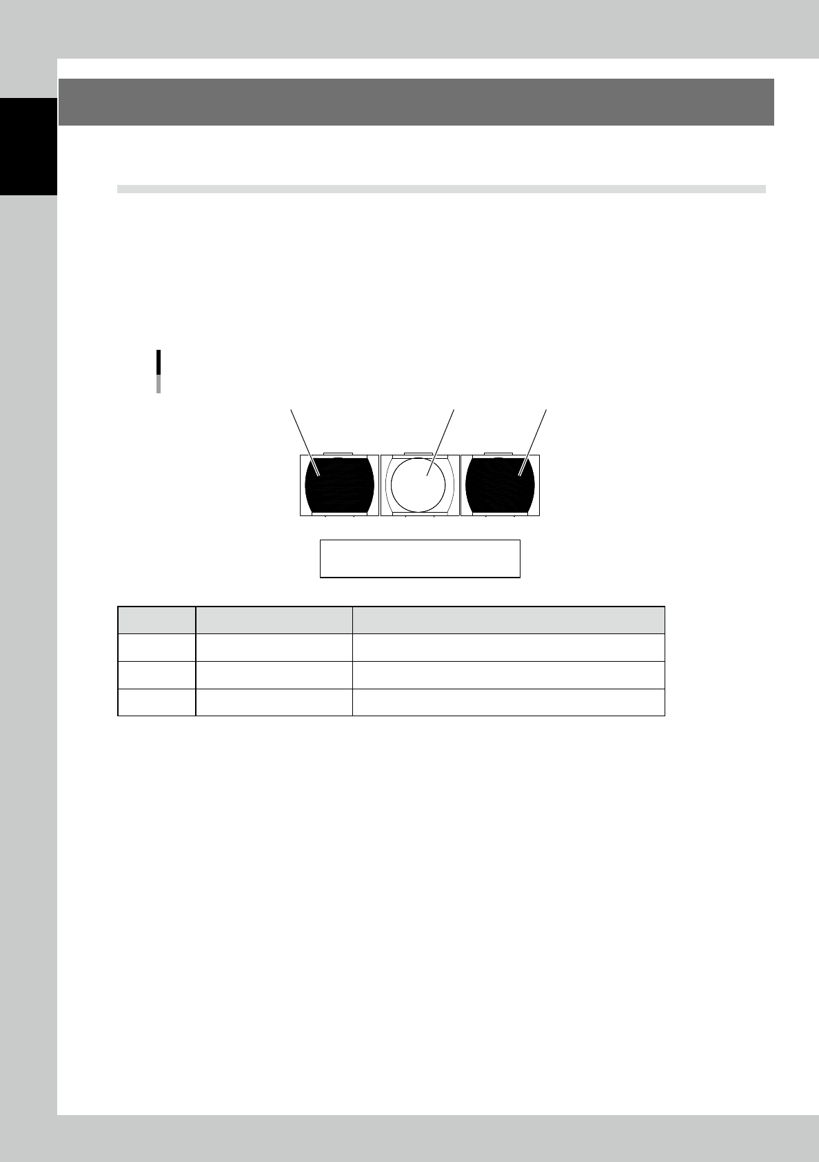
5.1.1 PLC switch panel
The PLC switch panel is located when the keyboard table is opened. It is usually not used. Use the switch
when your personal computer does not operate due to the personal computer failure of machine’s main body.
Switch panel
1
23
Reset / Stop / Start
23106-KMN-00
Machine name Motion and check
1 [Start] button Starts the PASS mode.
2 [Stop] button Stops the PASS mode.
3 [Reset] button Reset the home position.
1-11
1
Overview and maintenance of machine
5.1.2 Adjustment of the conveyor width
Adjustment of conveyor width is done manually in case of personal computer failure.
Insert the conveyor board and adjust to the board width by using the handwheel handle.
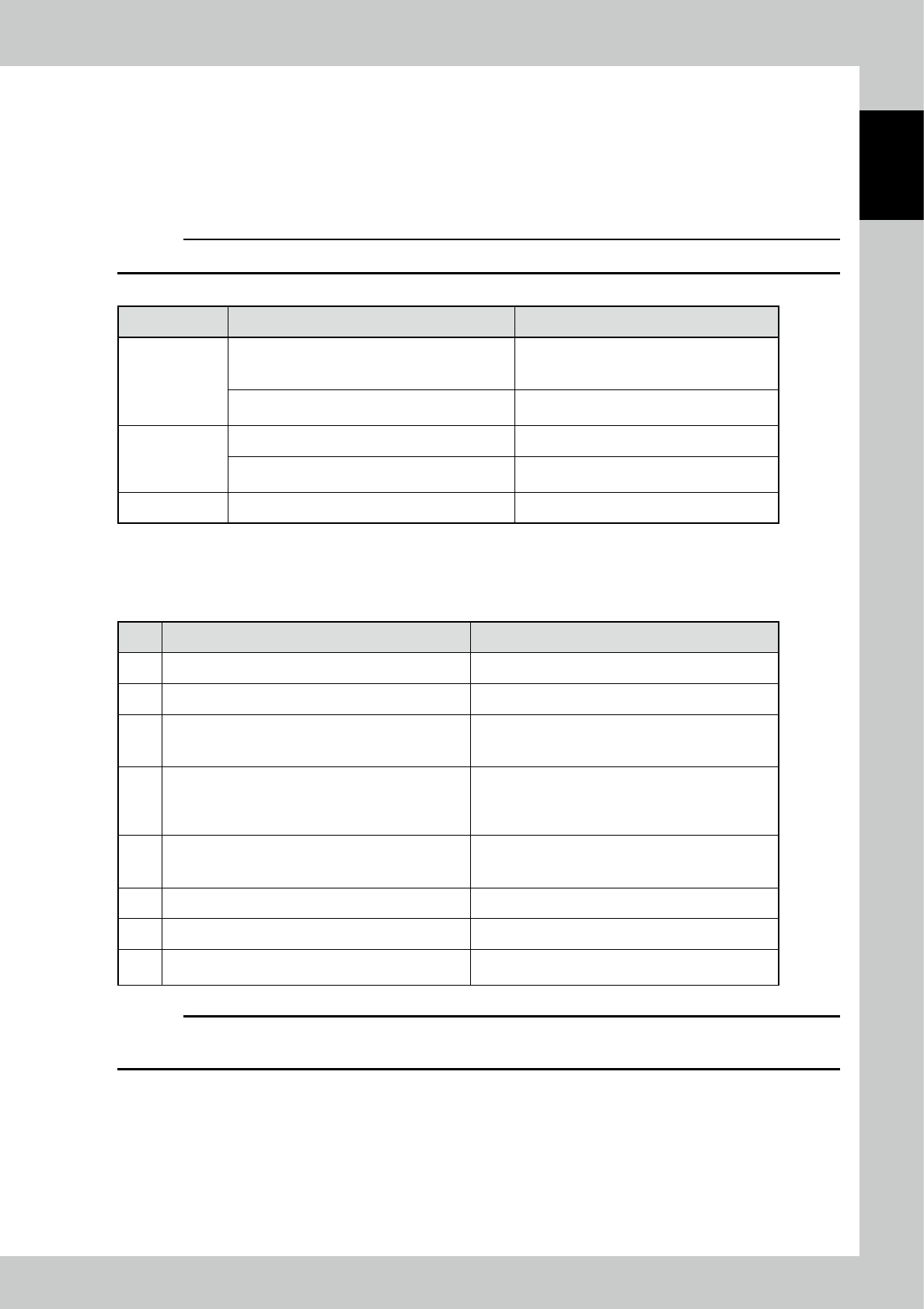
5.1.3 Explanation of switches
c
CAUTION
Switches are enabled only in the forced PASS mode.
Function Motion of the device by the button operation Remarks
[Start] button
When preparation is OFF (the power of the drive
section is OFF), turns on the power of the drive
section.
When the power of the drive section is turned
on, the lamp of the switch blinks.
When preparation is ON (the power of the drive
section is ON), starts the operation of the device.
The lamp of the switch lights up during the
device is in operation.
[Stop] button Stops the operation of the machine.
Starts the forced PASS mode in conjunction with
the breaker of the "primary power."
[Reset] button Resets the error display.
5.1.4 Operational procedure of forced PASS mode
No. Operation or status Motion and check
1 Turn off the breaker of the "primary power."
2 Check the conveyor width. Adjust the conveyor width by the manual wheel.
3
Turn on the breaker of the "primary power" by pressing
and holding the "Stop" button. (Hold the switch for over
three seconds.)
Changes to the PASS mode.
Start of initialization
→
Wait for about three seconds.
4 Press the [Start] button.
Power on of the drive section
→
Wait for about three
seconds.
The switch lamp blinks at the timing of startup is
available.
5 Press the [Start] button.
Starts the automatic operation (PASS mode).
The switch lamp of start lights up.
At this time, check that the tower lights up in "green."
6 By pressing the "Stop" button, the device stops. The switch lamp of start blinks.
7 To operate again, press the "Start" button.
8
For termination, check that boards are ejected, and
then turn off the breaker of the "primary power."
c
CAUTION
If you press the "Emergency stop" button and bring the machine to an emergency stop, release the lock of the
"Emergency stop" button and press the "Reset" button. Then, perform the procedure after the step 4 again.