YSi-SP_Ope_E.pdf - 第55页
2-18 2 Operation 3. Screen Configuration and Each Function 3.1 Screen Configuration 24220-KMN-00 T he figure shows the main tab menu located at the upper part of the screen. T ouch the desired tab to select it and jump t…
2-17
2
Operation
2.7 Shutdown of Inspection Machine
Follow the procedure below to shut down the inspection machine.
1. While the inspection machine is in a stop, touch the [shutdown] button at the upper right of the main menu screen for
one second to shut down the inspection machine.
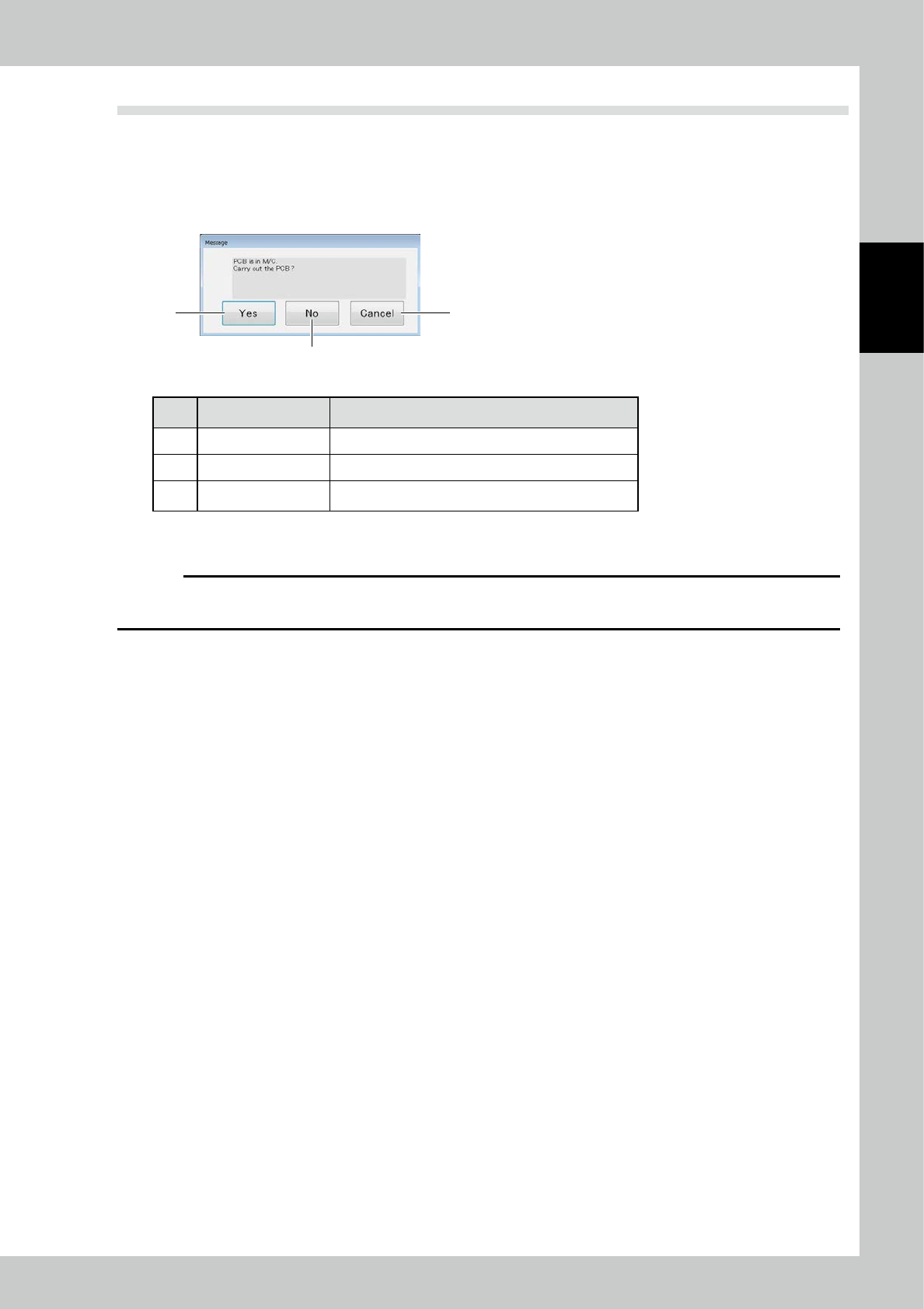
2. When the substrate in the apparatus to perform a shut down in the state of being clamped, the following message
appears.
2
1 3
24219-KMN-00
No Name Description of displayed item and functions
1 Yes After the substrate carry-out, and then shut down.
2 No Run the shutdown.
3 Cancel To cancel the shutdown.
3. After confirming the machine is shut down, open the front cover of the main body of the inspection machine and turn
off the main power off.
c
CAUTION
The inspection machine runs on Windows operating system. Before turning off the main power switch, be sure to check
that the operating system has been shut down.
2-18
2
Operation
3. Screen Configuration and Each Function
3.1 Screen Configuration
24220-KMN-00
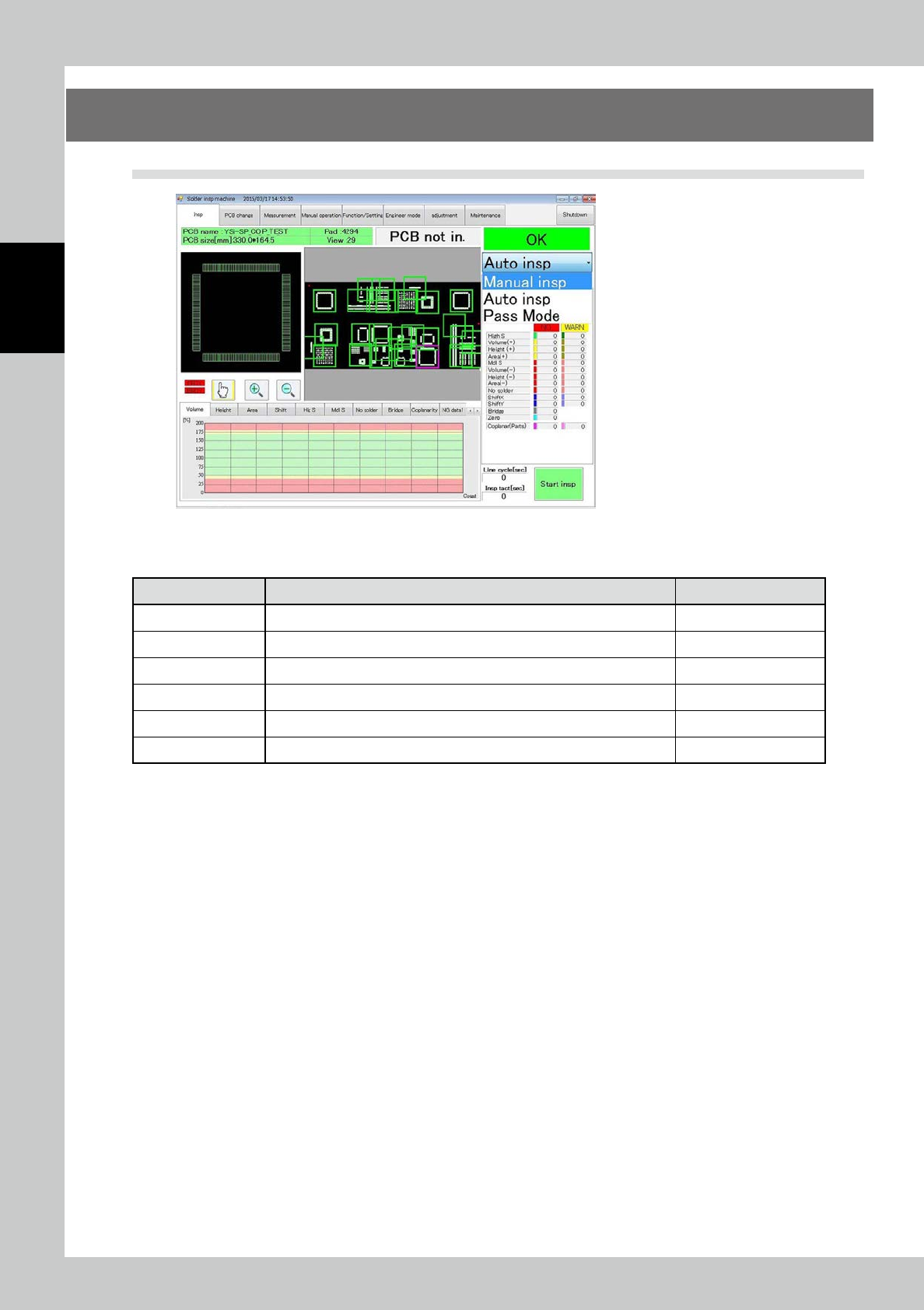
The figure shows the main tab menu located at the upper part of the screen. Touch the desired tab to select it
and jump to the corresponding menu screen.
Menu Option Description Refer to
Insp Check the image of the PCB being inspected and inspection results. "3.2 Inspection"
PCB change Change the PCB (inspection program). "3.3 PCB Change"
Measurement Measure the inspection results with 3D or 2D images. "3.4 Measurement"
Manual operation Load/unload the PCB, adjust the conveyor width, or adjust the XY table. "3.5 Manual Operation"
Function/Setting Enter or adjust the settings about the main body of the inspection machine. "3.6 Function/Setting"
Engineer mode Create or edit inspection programs, specifications or part library. "3.7 Engineer Mode"
2-19
2
Operation
3.2 Inspection
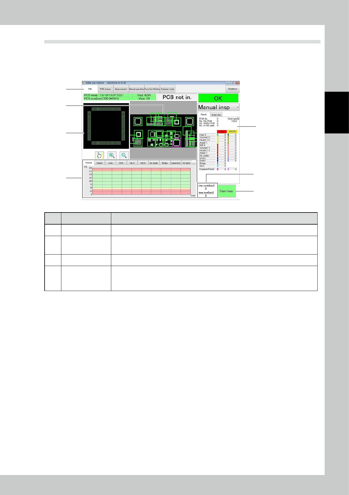
Items displayed on the inspection screen and functions are described. On the inspection screen, two images
are displayed at the upper part of the screen, while a histogram showing the inspection result is displayed at
the lower part. The histogram shows one of seven inspection items through selection with a tab. In addition,
inspection results of the PCB and so on are displayed on the right part of the screen.
7
1
5
6
2
3
4
24221-KMN-00
No Name Description of displayed item and functions
1 PCB data The PCB name, size, number of fields of view of inspection and comment are displayed.
2 PCB image
The image of the entire PCB is displayed. The pad image is displayed in white, while the field of view
is indicated with a blue frame. The active field of view is indicated with a pink frame, and it moves
according to the progress of inspection.
3 Image of field of view The image of the field of view being inspected is displayed.
4 Histogram
The inspection result is displayed in a histogram. In the automated inspection mode, the inspection
result is displayed continuously. The maximum value, minimum value or mean can be displayed.
(For the setting, refer to "3.6.5 Chart Setting".)
The displayed graph changes according to the inspection item each time the tab is touched.