YSi-SP_Ope_E.pdf - 第81页
2-44 2 Operation 3.6.5 Char t Setting Enter graph settings displa yed on the inspection tab. 1 3 4 5 2 24255-KMN-00 No Name Description of displayed item and functions 1 Graph type The graph type to be displayed can be s…
2-43
2
Operation
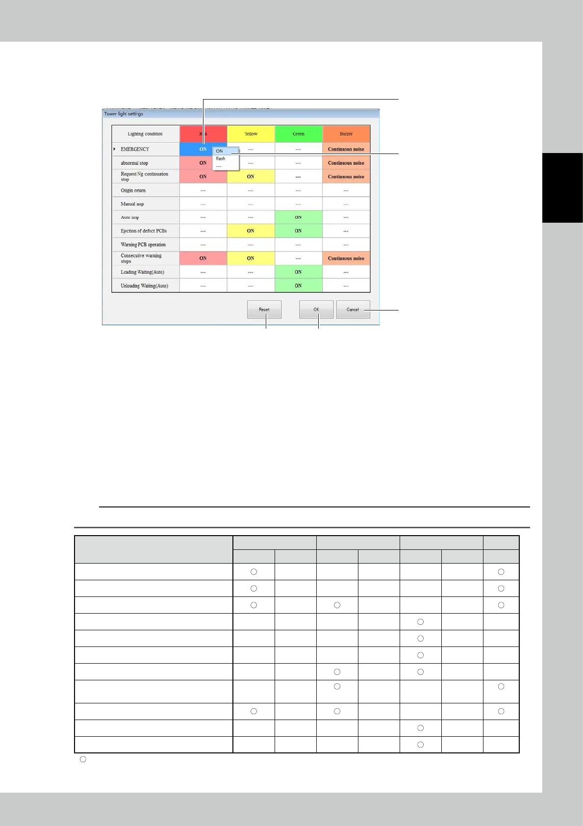
3.6.4 Tower Light Setting
Clicking the Change lighting condition button opens the "Tower Light Setting" screen.
1
2
5
4, 6
7
24254-KMN-00
●
To change any of the lighting conditions.
1. Select the item in regard to which you want to make a change.
2. Choose a tower light color and condition for the buzzer.
3. To make any other changes, repeat steps 1 to 2.
4. After the completion of setting, click OK.
●
To return to setting chosen at the factory,
5. Click Reset.
6. Clicking the OK button returns the machine to factory-selected setting.
●
To cancel setting that has been chosen
7. Click the Cancel button.
TIP
Settings listed in the table below can be changed.
Red Yellow Green Buzzer
Light up Flash Light up Flash Light up Flash
Emergency stop
Error-related stop
Contiguous defects
Return to home position
Individual operation
Automatic operation
Defective PCBs being ejected
Alarm generated
(3sec)
(3sec)
Machine shutdown due to contiguous alarms
PCBs being taken in
PCBs being ejected
: Indicates default setting.
2-44
2
Operation
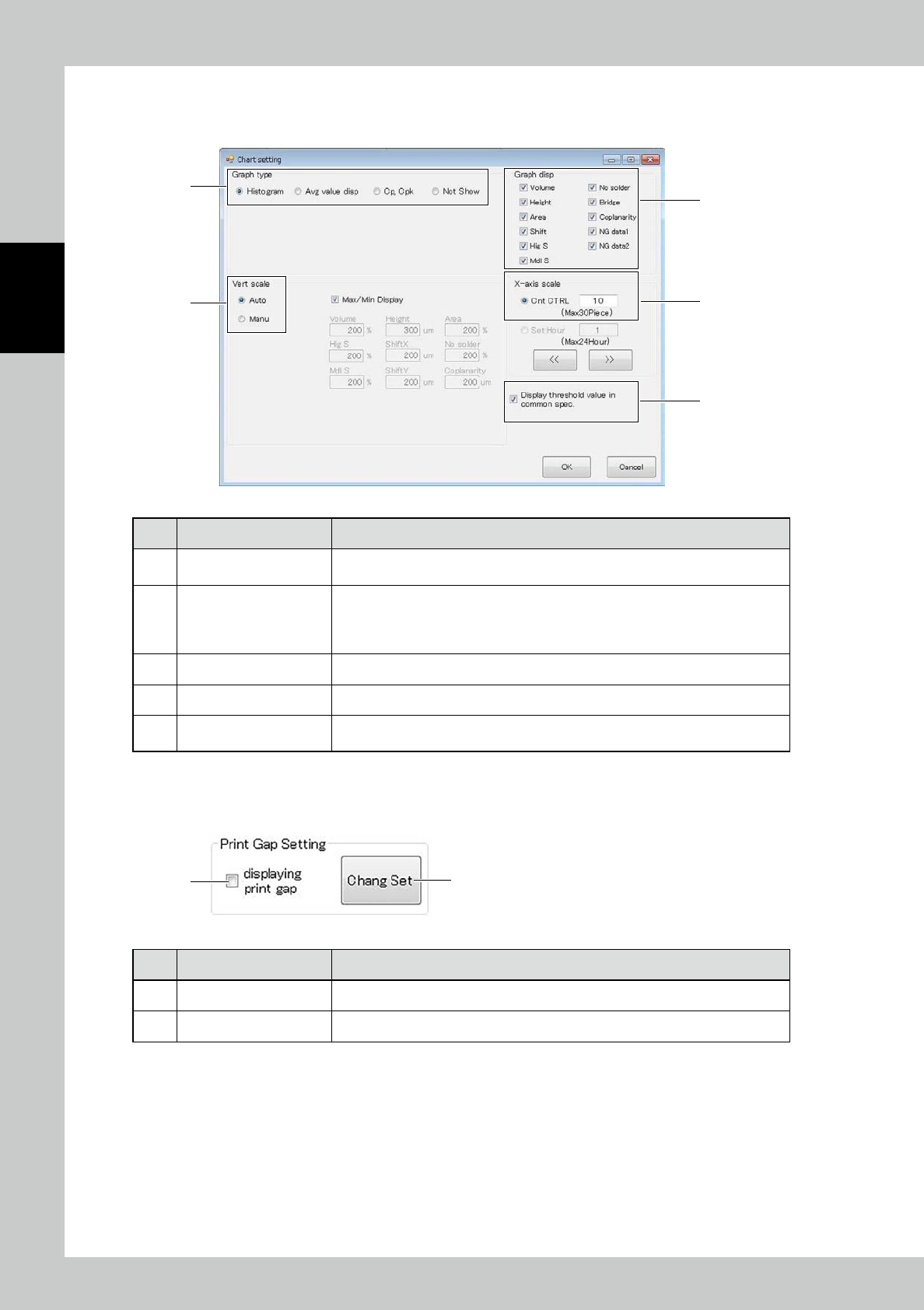
3.6.5 Chart Setting
Enter graph settings displayed on the inspection tab.
1
3
4
5
2
24255-KMN-00
No Name Description of displayed item and functions
1 Graph type
The graph type to be displayed can be selected among "Histogram," "Avg value
disp," "Cp, Cpk" and "Not Show."
2 Vert scale
Change the vertical scale setting of the graph according to each item.
Select Auto to automatically adjust the scale.
Select Manu to display the graph at the designated scale.
Place a check mark at Max/Min Display to plot the maximum and minimum values.
3 Graph Display The graph of the inspection items with check mark are displayed.
4 X-axis scale Change the X-axis display count setting according to the count or hours.
5
Display threshold value in
common spec
If the spec in use is one type, the spec is displayed.
3.6.6 Print Gap Setting
●
Function/Setting of main screen tab
1 2
24256-KMN-00
No Description Refer to
1 Displaying print gap Print gap display/non-display setting
2 Chang Set Change the PCB rotation axis setting of the printing machine.
2-45
2
Operation
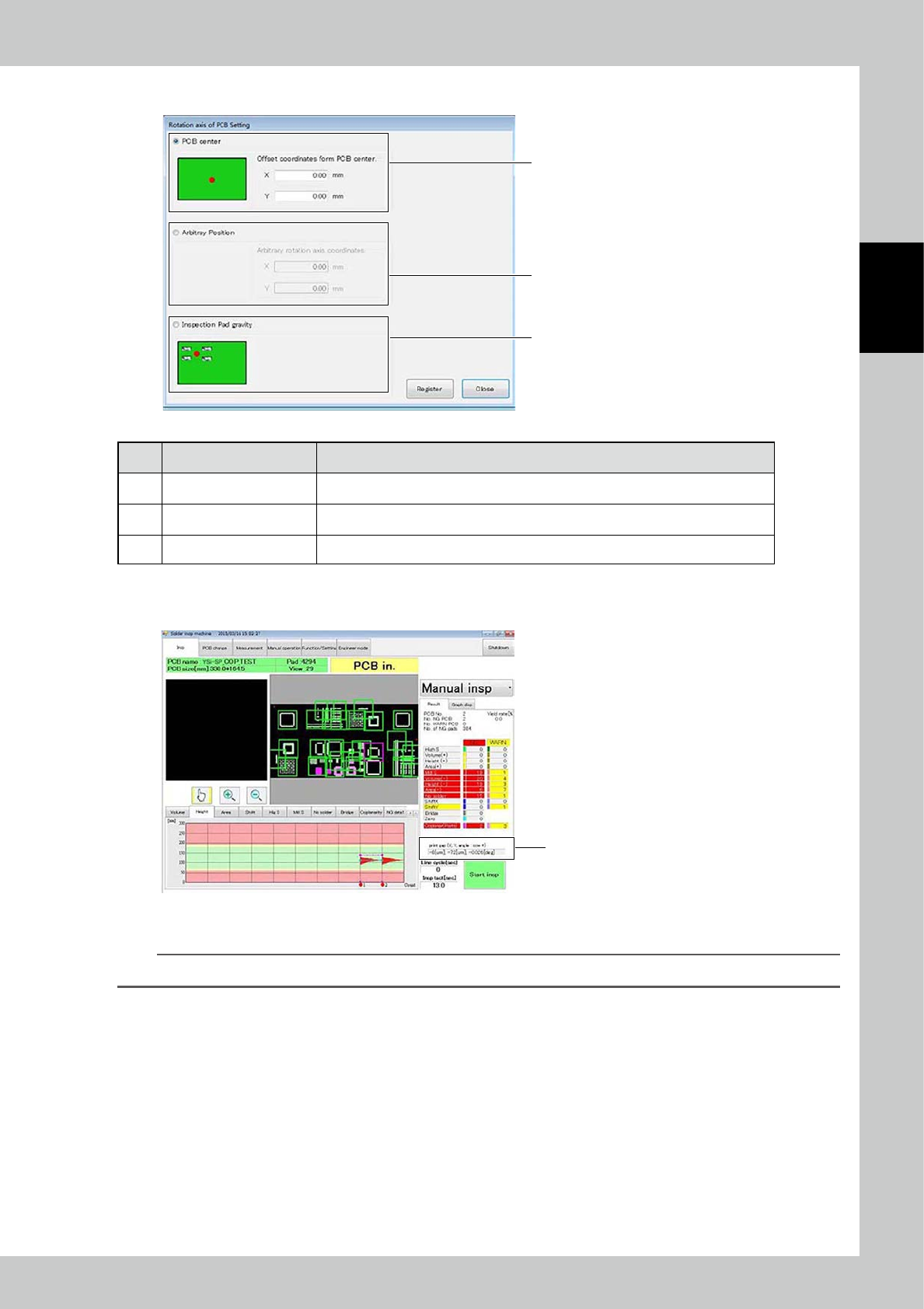
The PCB rotation axis setting of the printing machine is entered.
1
2
3
24257-KMN-00
No Description Refer to
1 PCB Center Define the rotation axis in the PCB center. Offset coordinates can be entered, too.
2 Arbitray Position Define the rotation axis in an arbitrary position from the zero point of the PCB (0, 0).
3 Inspection Pad gravity Define the rotation axis in the center of gravity of all inspection pads.
●
Result view
The result is displayed in position 1 of the main screen after inspection.
Result view
24258-KMN-00
Displayed content: X gap [μm], Y gap [μm], theta (angle) gap [deg]
TIP
The positive value indicates counterclockwise rotation.