YSi-SP_Ope_E.pdf - 第96页
2-59 2 Operation 4. Inspection Program 4.1 Creating new PCB data (printed PCB) T he method for creating an inspection program using the taken image of a printed PCB is described. 1. Pad extraction T ouch the spec data [E…
2-58
2
Operation
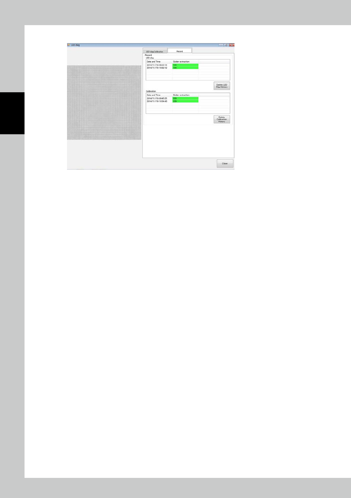
3. Click on the "Record" tab to check the record of light source diagnosis and calibration.
24278-KMN-00
2-59
2
Operation
4. Inspection Program
4.1 Creating new PCB data (printed PCB)
The method for creating an inspection program using the taken image of a printed PCB is described.
1. Pad extraction
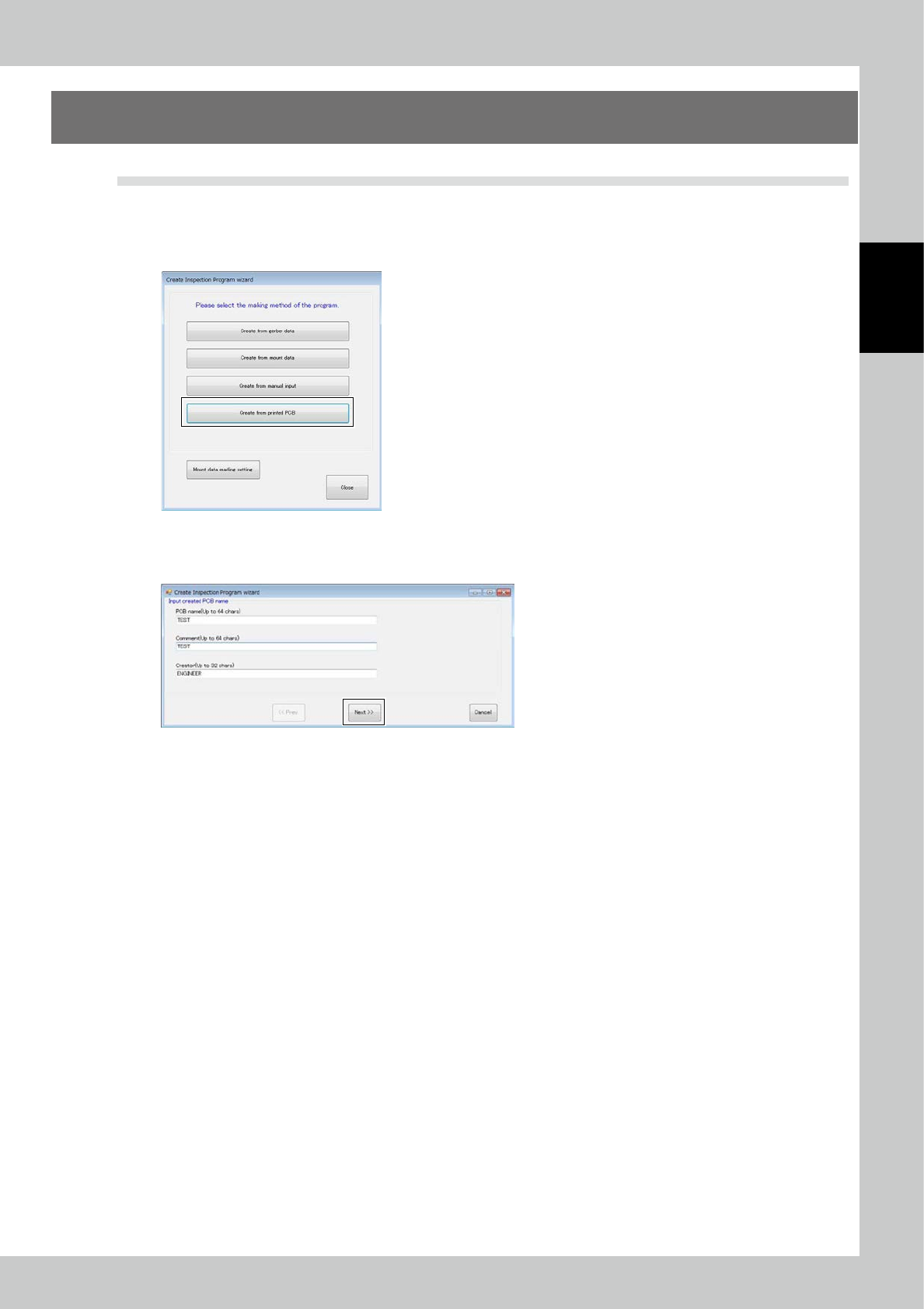
Touch the spec data [Edit] button on the engineer mode screen. The figure shown below is displayed.
24279-KMN-00
Select Printed PCB and click on the [Next] button.
Enter the PCB name and click on the [Next] button.
24280-KMN-00
2-60
2
Operation
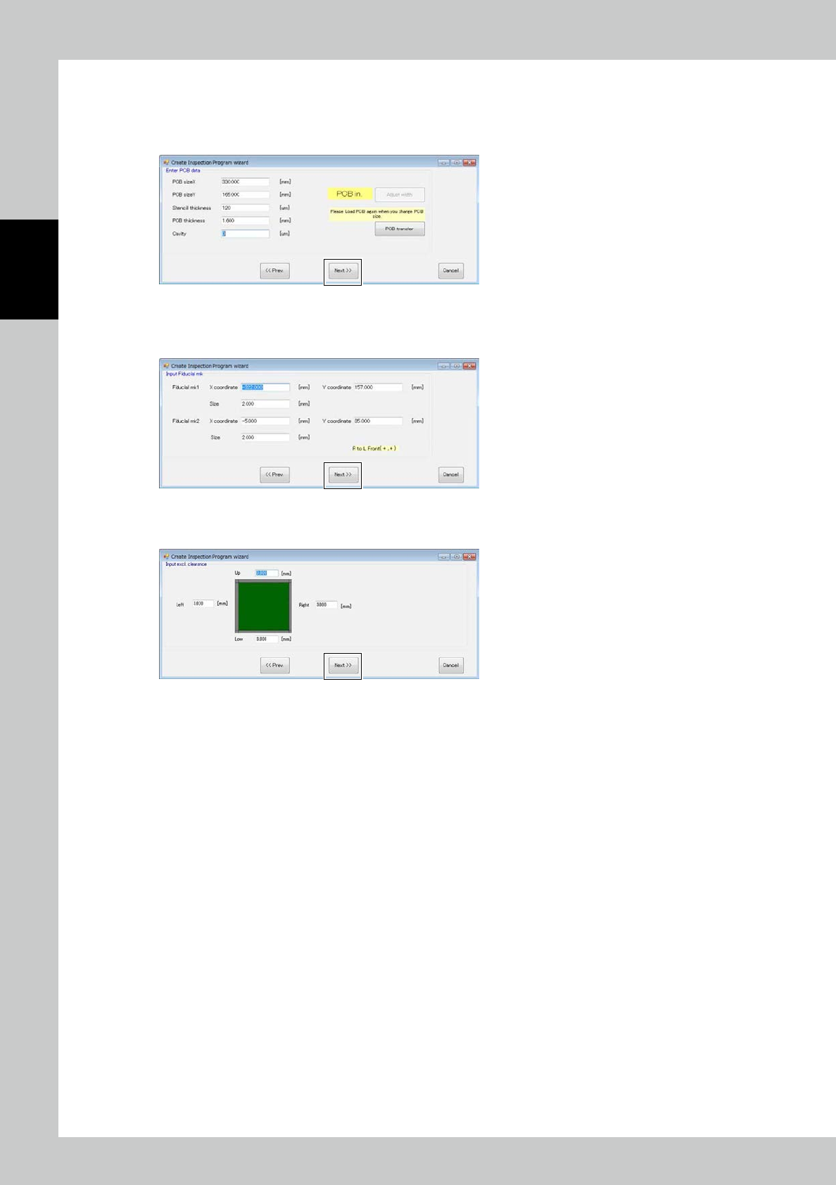
Enter dimension of PCB and thickness of metal mask.
Repeat the step to choose a width setting if required.
Convey PCBs to take them in the machine.
Click the [Next] button.
24281-KMN-00
Enter the coordinates and diameter of the fiducial mark. (Values of the previous PCB are already set.) Click on the
[Next] button.
24282-KMN-00
Enter the margins of the PCB where pad extraction is unnecessary. Click on the [Next] button.
24283-KMN-00