YSi-SP_Ope_E.pdf - 第138页
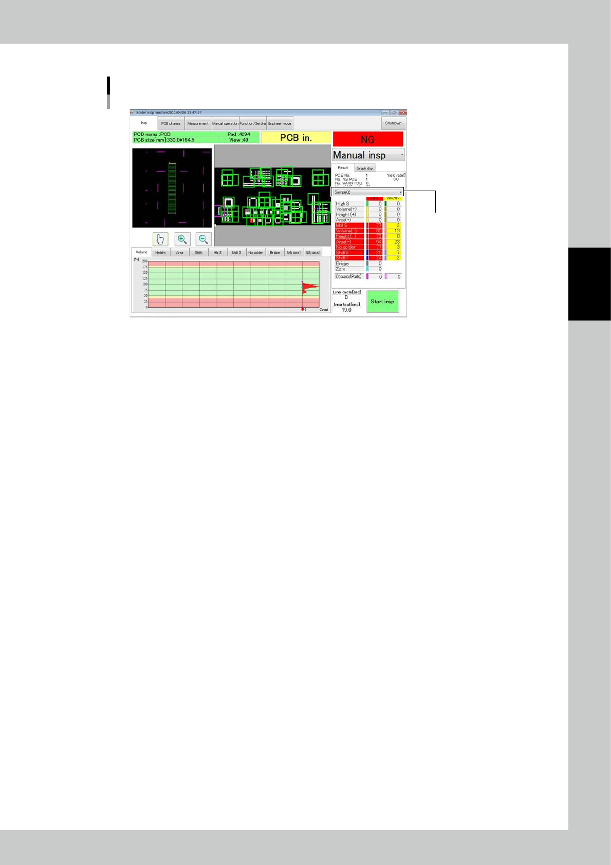
3-3 3 Optional Functions After inspection is finished, the 2D code is displa yed in the position shown in the figure. The 2D code is displayed here. 2D code check 24302-KMN-00
3-2
3
Optional Functions
1.2 2D Code Inspection Specifications
2D code to be used QR code MicroQR or DATAMATRIX
Number of 2D codes inspected The mount block + 1 place can be registered.
1.3 How to Conduct 2D Inspection
Follow the inspection procedure below to conduct 2D code inspection.
1
Select Engineer Mode
→
[Edit]
→
[PCB edit]
→
[PCB data]
→
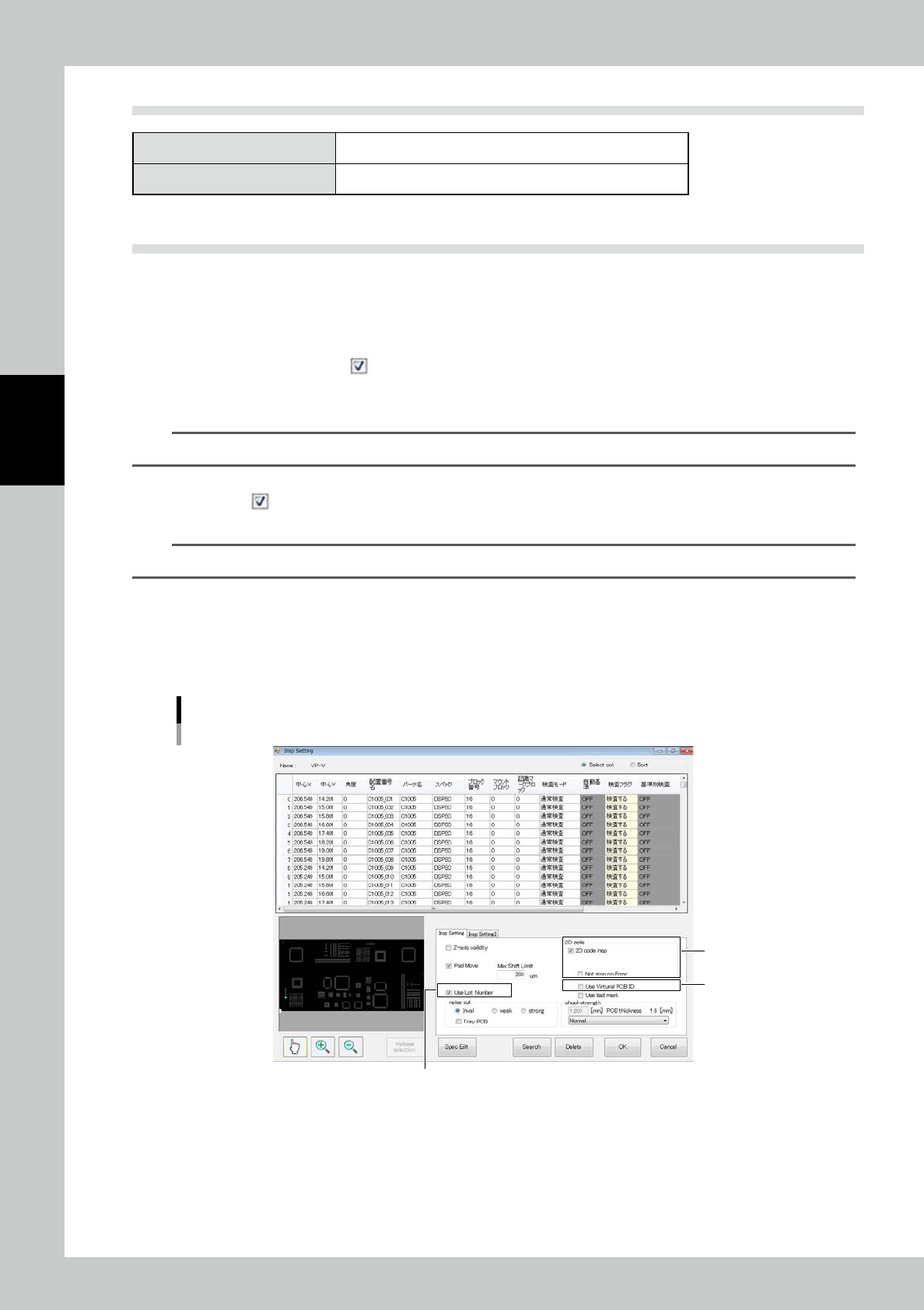
Insp Setting in this
order. The screen shown in Fig is displayed.
1. Place a check mark ( ) at "2D code insp".
2. Making a check mark on “Use Lot Number”, random lot numbers shall be written on the transition
data.
TIP
Setting for lot numbers can be executed every time switching product brands.
3. To use the virtual PCB ID (fixed character string + counter ID) instead of the 2D code, place a check
mark (
) at "Use Virtual PCB ID."
(Both virtual substrate ID and 2D code can not be used at same
time.)
TIP
Setting for virtual substrate ID can be executed every time switching product brands.
2
Select the engineer mode and light amount adjustment (refer to "1.4 Light Amount
Adjustment") to adjust the coordinates of the 2D code and light amount.
3
Execute inspection to start inspection of the PCB edge, fiducial mark, 2D code and
inspection pad in this order.
2
1
3
Insp Setting screen
24301-KMN-00
3-3
3
Optional Functions
After inspection is finished, the 2D code is displayed in the position shown in the figure.
The 2D code is displayed here.
2D code check
24302-KMN-00
3-4
3
Optional Functions
1.4 Light Amount Adjustment
1. Light amount adjustment
Select Engineer Mode
→
[Edit]
→
[Light Amount Adjustment]
→
"Special insp" tab
→
[2D code] in this order.
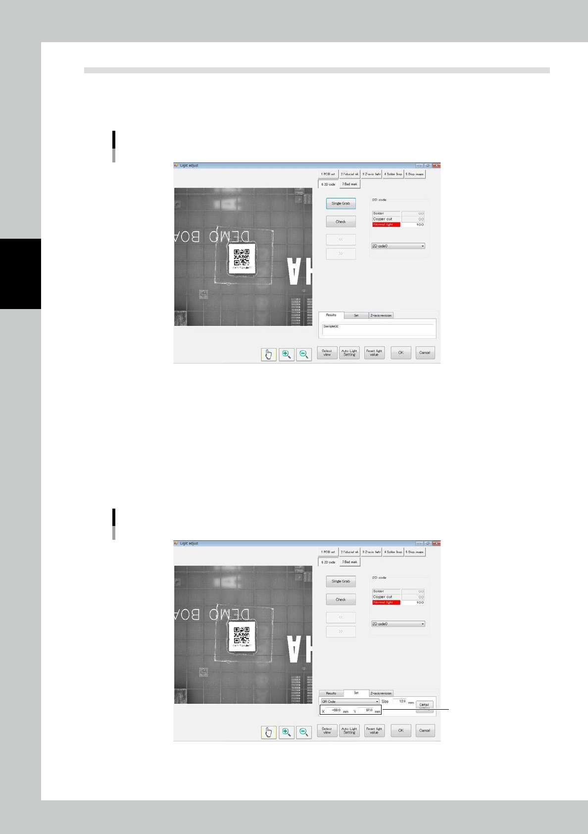
The screen shown in Fig. is displayed.
Light amount adjustment screen
24303-KMN-00
2. Registering coordinates
Adjust so that the 2D code coordinates are in the inspection view field.
If the 2D code is in the inspection view field, there is no need for adjustment.
Enter each of the X and Y coordinates.
※ Coordinates
From zero position of the PCB,
X: Positive toward the right on the screen, negative toward the left
Y: Positive toward the top of the screen, negative toward the bottom.
Coordinate adjustment screen
Coordinates
24304-KMN-00