YSi-SP_Ope_E.pdf - 第89页
2-52 2 Operation 3.6.12 Maintenance display Setting up for announce displa y and updating for coming replace timing on the maintenance screen. 1 2 3 4 5 6 7 8 24270-KMN-00 No Name Description of displayed item and functi…
2-51
2
Operation
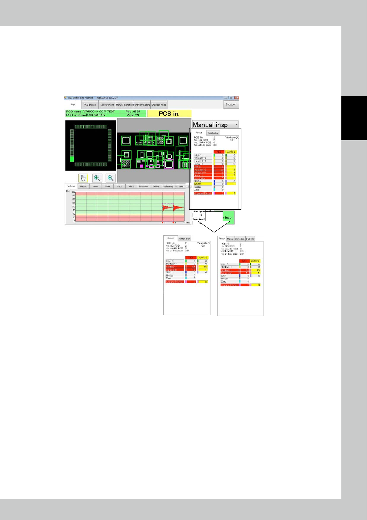
3.6.11 PCB insp result disp
Select Simple Disp to show the results of aggregation as shown below.
Solder (+) : The sum of volume +, average height + and area + is displayed.
Solder (-) : The sum of volume -, average height -, area - and blur is displayed.
Other inspection items are displayed similarly to the case of standard display.
The marked part changes in the simple display mode.
Simple Disp
Standard Disp
24269-KMN-00
2-52
2
Operation
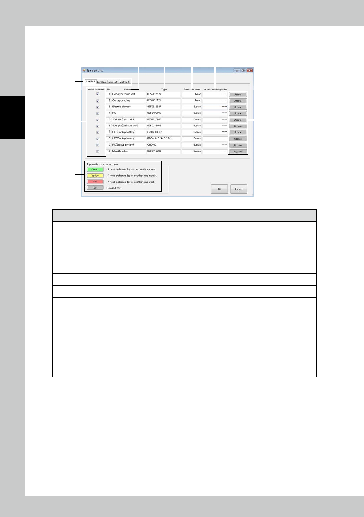
3.6.12 Maintenance display
Setting up for announce display and updating for coming replace timing on the maintenance screen.
1
2
3 4 5 6
7
8
24270-KMN-00
No Name Description of displayed item and functions
1 List tab
Displaying for the registered maintenance parts.
• List Tab1 : Displaying the registered parts from No. 1 to 10.
• List Tab2 : Displaying the registered parts from No. 11 to 20.
• List Tab3 : Displaying the registered parts from No. 21 to 30.
2 Announcement Switching ON/OFF of message display.
3 Name Displaying the parts name should be replaced.
4 Type Displaying the parts type should be replaced.
5 Effective years Displaying the parts replace interval.
6 A next exchange day Displaying the coming replace date.
7 Update button
Updating next parts replace date.
This button shall be selected after the maintenance parts are replaced.
In case of selection g the button, “Selected current date + Valid Date”
shall be displayed the coming replace date.
8 Explanation of a button color
The rest date to coming replace interval shall be with the colored buttons.
• Green : The coming replace date is more than one month.
• Yellow : The coming replace date is in one month.
• Red : The coming replace date is in one week.
The maintenance parts displayed with yellow and red colored buttons are in the
announce condition.
2-53
2
Operation
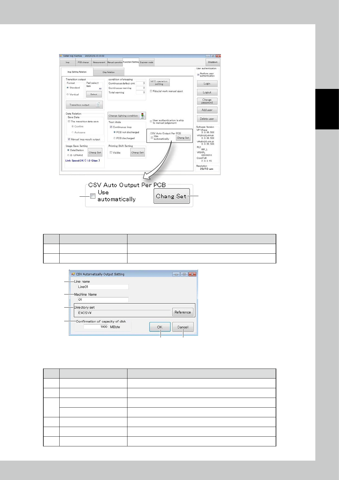
3.6.13 CSV Auto Output Per PCB
Items displayed on the CSV Auto Output Per PCB ,and functions are described.
1
2
24271-KMN-00
■
Explanation of a screen
No Name Content
1 Use Auto Output Per PCB Place check mark for use auto output per PCB.
2 Change Set Changing the setting for CSV output.
1
2
3
4
5 6
24272-KMN-00
■
Explanation of a screen
No Name Content
1 Line name Setting up the line name for CSV output.
2 Machine name Setting up the machine name for CSV output.
3
Directory set Displaying the directory for CSV output.
[Reference] button Changing the directory for CSV output.
4 Confirmation of Capacity of disk When it approaches full up the capacity, the error message is displayed.
5 [OK] button Execution of setting.
6 [Cancel] button Canceling the setting.