YSi-SP_Ope_E.pdf - 第48页
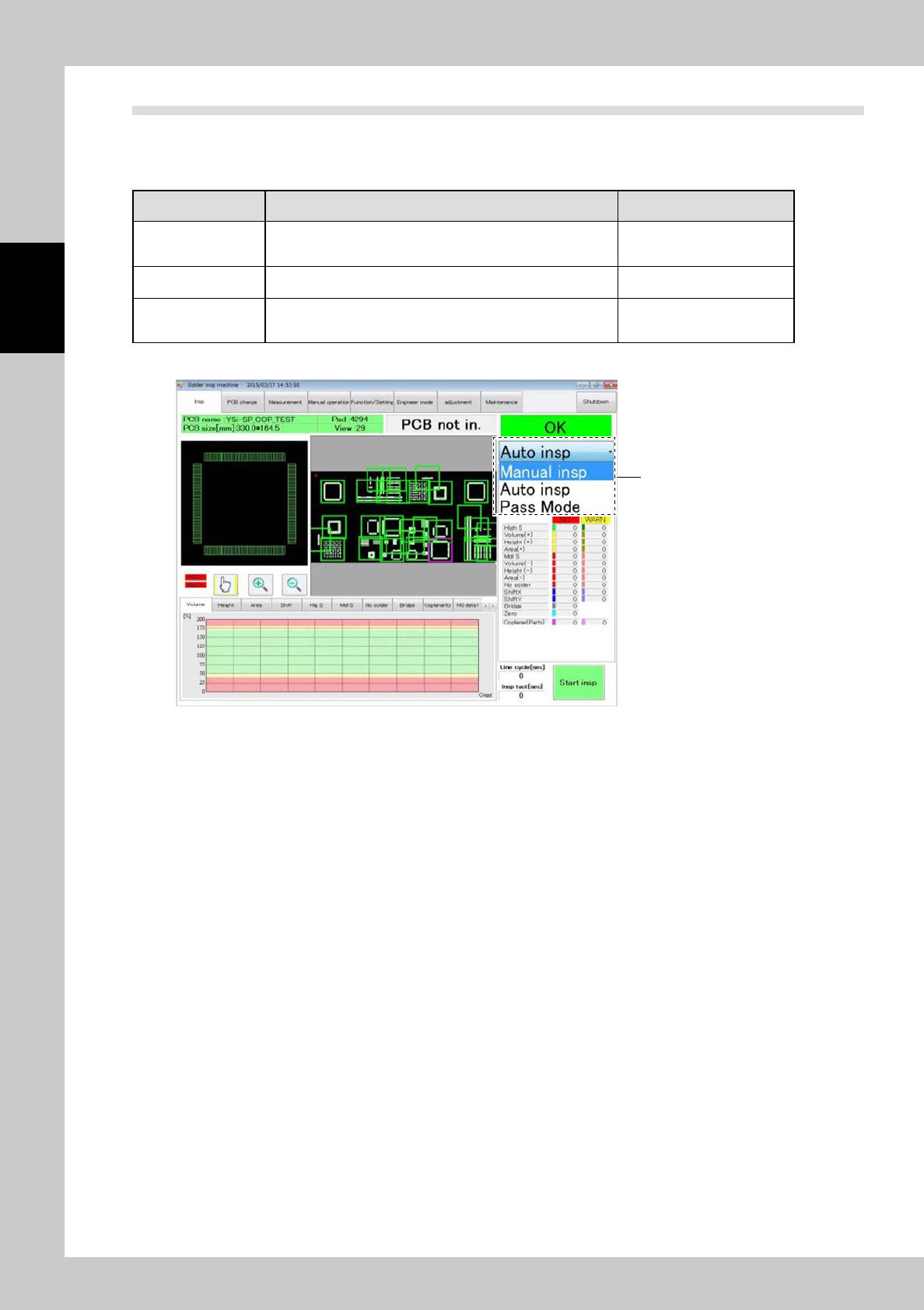
2-11 2 Operation 2.6.1 Standalone Inspection 1. Execution of inspection 3 2 1 24209-KMN-00 1 T ouch the inspection tab to open the inspection screen. 2 Select standalone inspection from the pull-down menu. 3 T ouch the […
2-10
2
Operation
2.6 Inspection
After selecting the inspection mode and loading the PCB into the machine, execute inspection.
There are three inspection types: standalone inspection, automatic inspection and pass mode. Each mode is
described below.
Inspection mode Description of inspection Refer to
Standalone inspect
The inspection machine operates offline without relations to the
pre- and post-processes. You can edit inspection programs in
this mode.
"2.6.1 Standalone Inspection"
Automatic inspection
PCBs are inspected continuously while communications are
made with pre- and post-processes.
"2.6.2 Automatic Inspection"
Pass mode
While the procedure taken with the pre- and post-processes is
the same as that of the automatic inspection mode, inspection
is not conducted.
"2.6.3 Pass Mode"
Select each mode from the pull-down menu on the inspection screen.
Pull-down menu
24208-KMN-00
2-11
2
Operation
2.6.1 Standalone Inspection
1. Execution of inspection
3
2
1
24209-KMN-00
1
Touch the inspection tab to open the inspection screen.
2
Select standalone inspection from the pull-down menu.
3
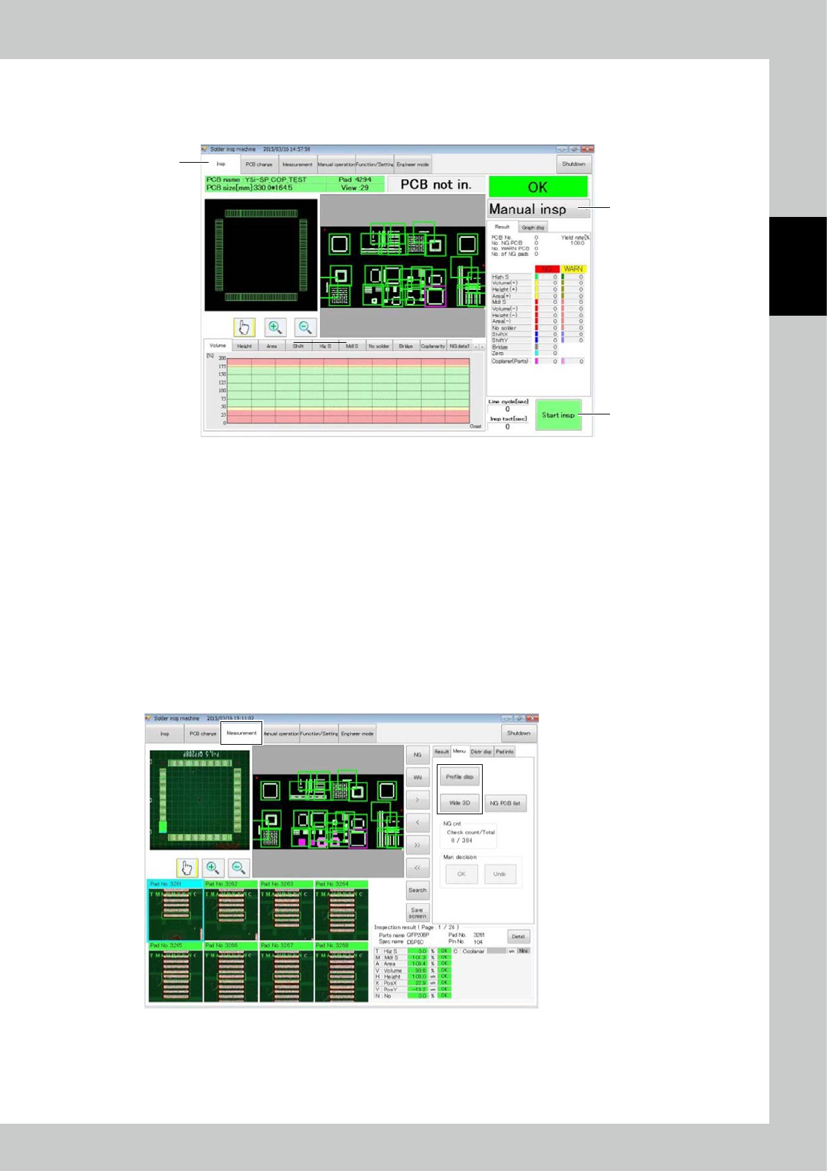
Touch the [Start insp] button to start inspection.
2. Result of inspection
To view the result of inspection of the PCB, touch “Measurement” on the main menu to open the measurement screen.
The result confirmation method includes two variations: profile display and wide-area measurement.
In both methods, the inspection result is displayed in a 3D image.
To execute profile display or wide-area measurement, open the measurement screen and touch either the [profile display]
or [wide area measurement] button on the right side of the screen. To open the profile display screen, you can touch the
corresponding pad screen twice.
24210-KMN-00
2-12
2
Operation
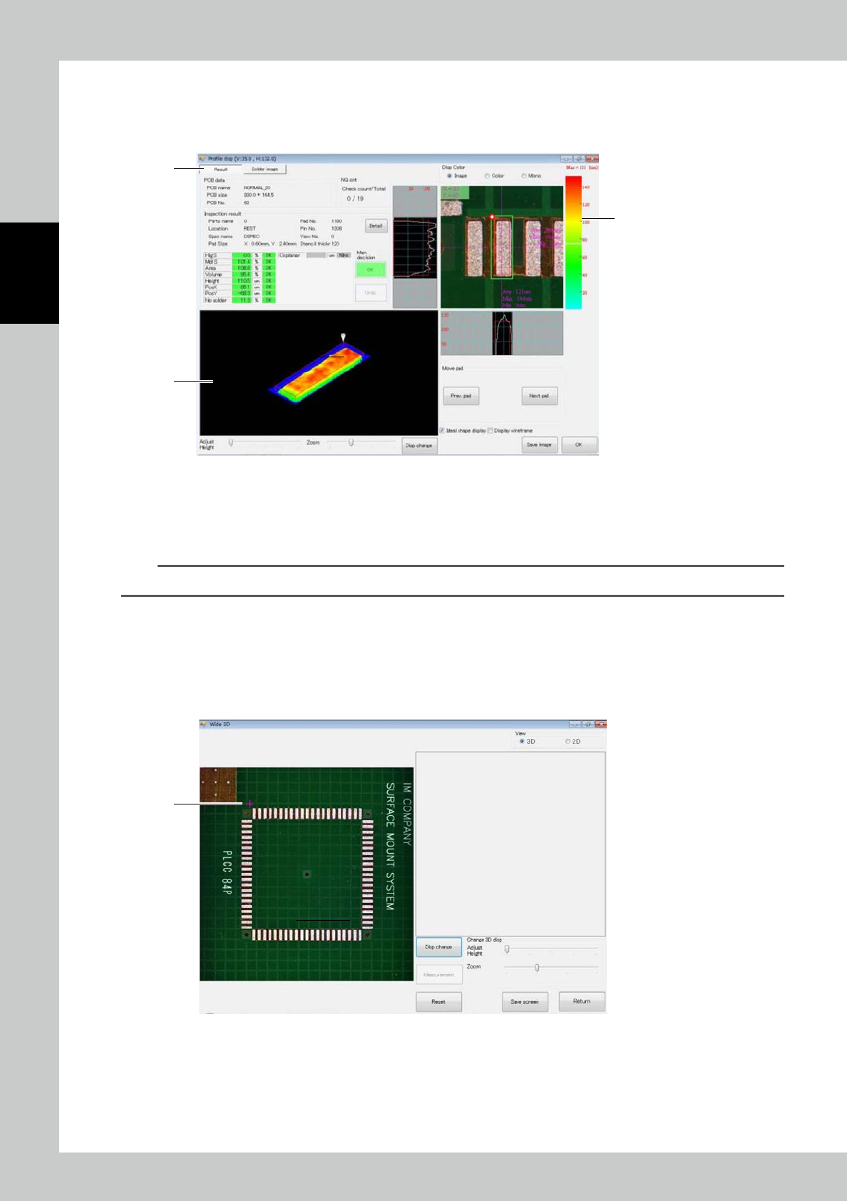
a. Profile display
Touch the [Profile disp] button or touch the desired pad on the field of view screen or each pad screen twice. The screen
shown below is displayed.
1
3
2
24211-KMN-00
1. This is a 3D image of the solder. Slide a finger along the image to change the displaying angle vertically or horizontally
over 360
°
as you need.
2. The solder height is indicated with the color gradation. (Red [high] - blue [low])
3. This is the pad inspection result.
TIP
For details of profile display screen, refer to "3.4.1 Profile Screen".
b. Wide 3D
Touch the [Wide 3D] button to display the screen shown below. With Wide 3D, you can view the 3D image of a desired
area.
Select the measurement range with the image displayed on the left side.
1. Determine the starting point. Touch the desired starting point. A red cross is displayed.
1
24212-KMN-00