YSi-SP_Ope_E.pdf - 第95页
2-58 2 Operation 3. Clic k on the "Record" tab to check the record of light sour ce diagnosis and calibration. 24278-KMN-00
2-57
2
Operation
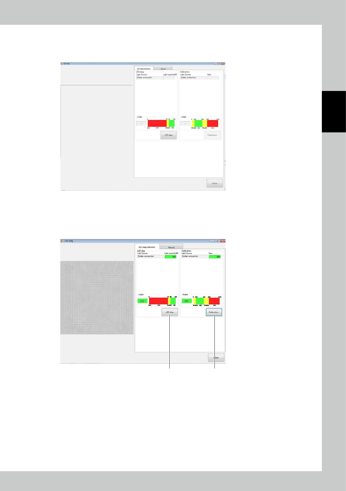
3.7.2 LED diag (Option)
Place a jig for checking the light source and touch the LED diag button. The screen shown below is displayed.
During light source diagnosis, you can check deterioration of the LED.
24276-KMN-00
1. Press the LED diag button. Results are displayed in the Judge field. If OK is displayed, there is no problem; you can
continue to use.
2. If NG is displayed, make calibration.
If NG is displayed even after calibration is made, LED replacement is necessary.
Please contact Yamaha sales representatives.
21
24277-KMN-00
2-58
2
Operation
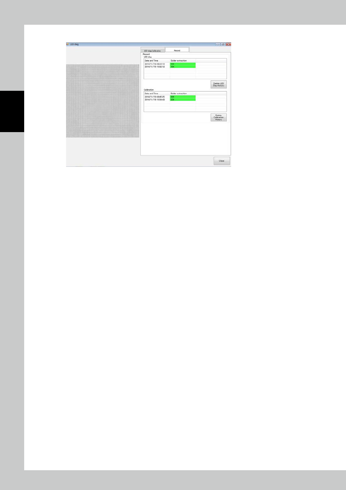
3. Click on the "Record" tab to check the record of light source diagnosis and calibration.
24278-KMN-00
2-59
2
Operation
4. Inspection Program
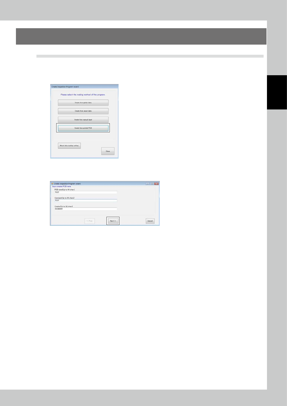
4.1 Creating new PCB data (printed PCB)
The method for creating an inspection program using the taken image of a printed PCB is described.
1. Pad extraction
Touch the spec data [Edit] button on the engineer mode screen. The figure shown below is displayed.
24279-KMN-00
Select Printed PCB and click on the [Next] button.
Enter the PCB name and click on the [Next] button.
24280-KMN-00