YSi-SP_Ope_E.pdf - 第58页
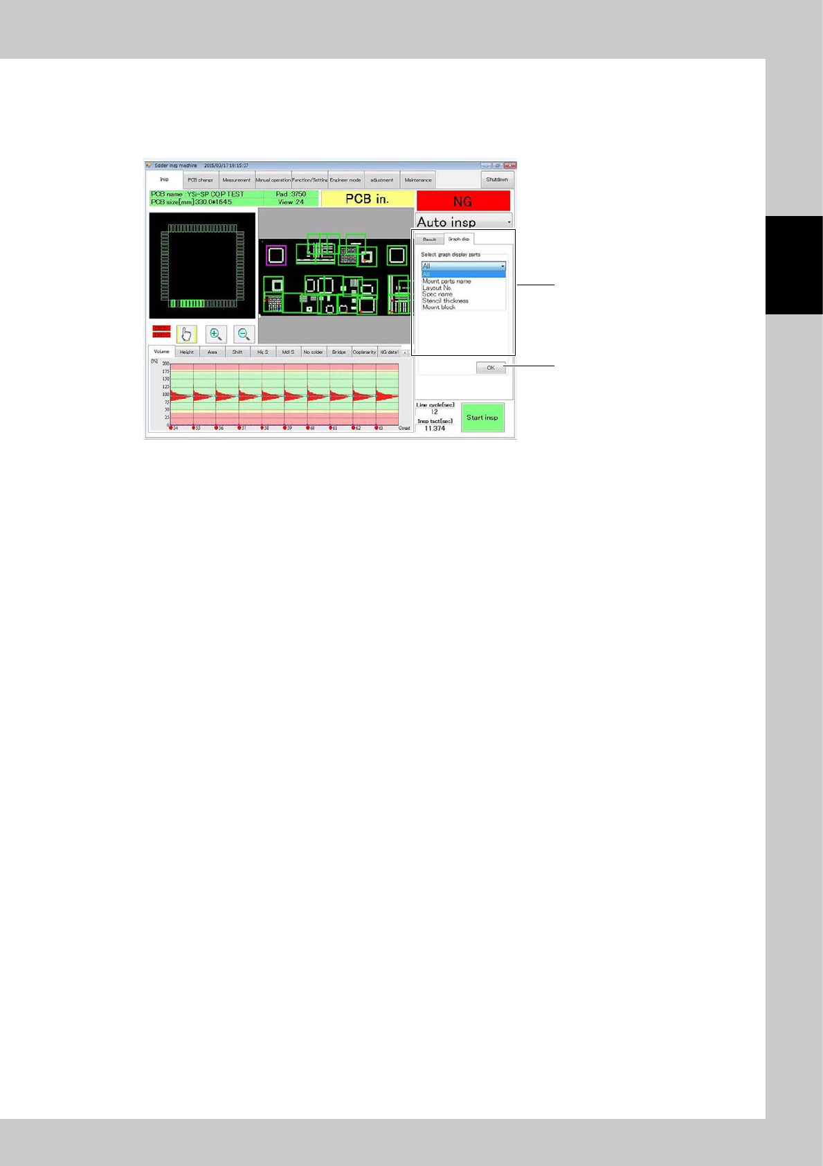
2-21 2 Operation T o c hange the graph view , you can select the Graph Disp tab as shown belo w . T he graph is dra wn according to the selected data. 1. Select the part from the list. 2. Press OK to update the gr aph vi…
2-20
2
Operation
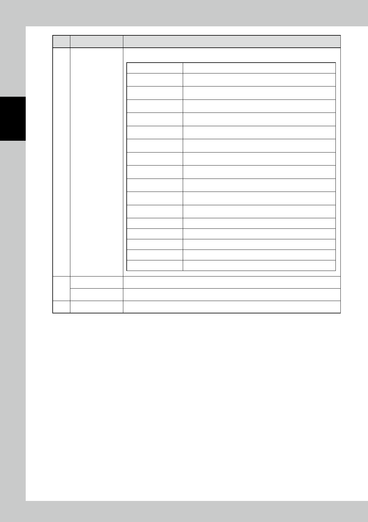
No Name Description of displayed item and functions
5
Results of inspection
of PCB
The inspection results are indicated in colors and the inspection quantity is displayed.
PCB No. The inspected PCB number is displayed.
Number of faulty PCBs
The number of faulty PCBs in the inspected PCBs is displayed
according to the inspection result.
Number of warning PCBs
The number of warning PCBs in the inspected PCBs is displayed
according to the inspection result.
Projection (High S) The number of pads judged to be a projection fault is displayed.
Blur (Low S) The number of pads judged to be a blur fault is displayed.
Volume (+)
The number of pads having a larger volume than the spec value is
displayed.
Height (+)
The number of pads having a larger average height than the spec value
is displayed.
Area (+)
The number of pads having an area larger than the spec value is
displayed.
Fade (Mdl S) The number of pads judged to be a fade fault is displayed.
Volume (-)
The number of pads having a volume smaller than the spec value is
displayed.
Height (-)
The number of pads having a smaller average height than the spec
value is displayed.
Area (-)
The number of pads having a volume smaller than the spec value is
displayed.
Shift X The number of pads deviating in the X direction is displayed.
Shift Y The number of pads deviating in the Y direction is displayed.
Bridge The number of pads judged to be a bridge fault is displayed.
No solder The number of pads judged to be a no-solder fault is displayed.
Coplanarity The quantity of parts judged to be a coplanarity fault is displayed.
6
Line cycle The time from PCB loading to the loading of the next PCB is counted.
Inspection tact The time from the start of inspection to the end of inspection is counted.
7 [Start insp] button Touch to start to inspect.
2-21
2
Operation
To change the graph view, you can select the Graph Disp tab as shown below.
The graph is drawn according to the selected data.
1. Select the part from the list.
2. Press OK to update the graph view according to selection.
2
1
24222-KMN-00
2-22
2
Operation
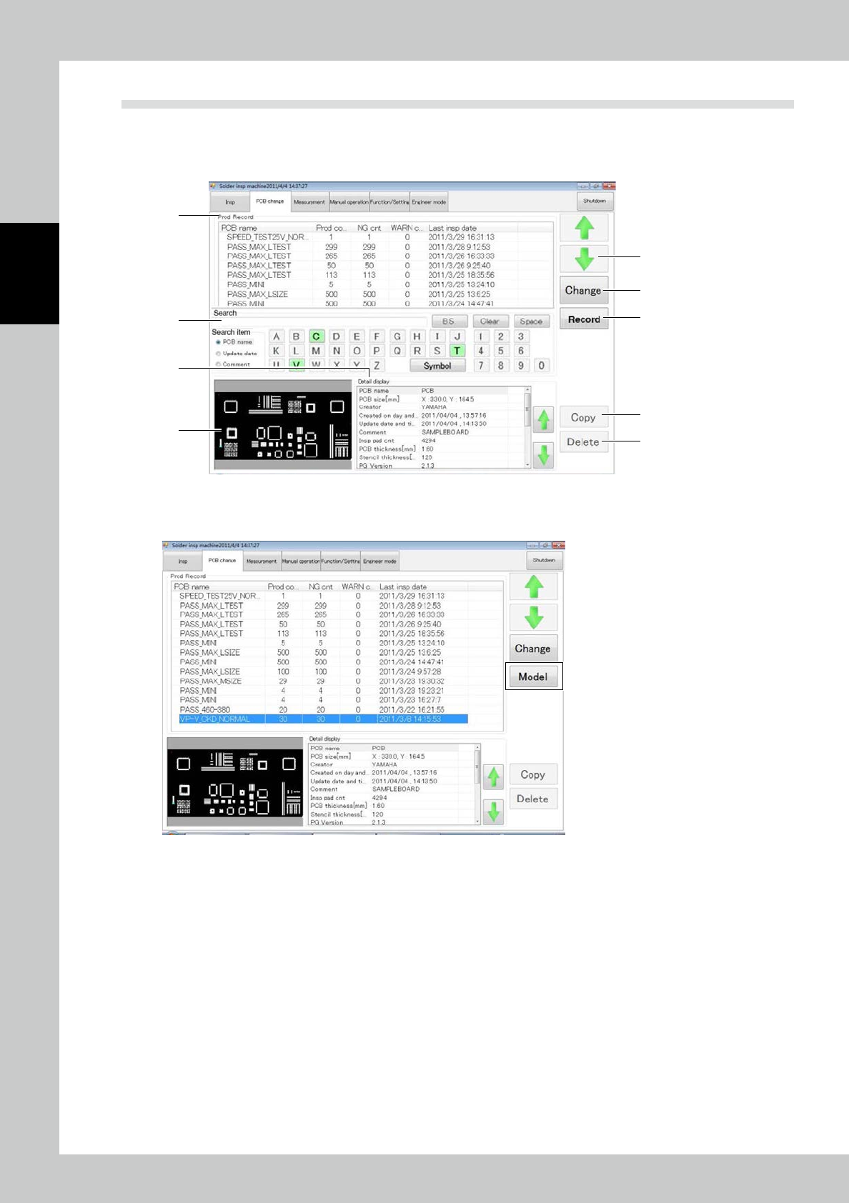
3.3 PCB Change
Items displayed on the PCB change screen and functions are described. The PCB list is displayed at the top of
the screen. Select the desired one. Or you can use arrow buttons or search function to select. After selecting
the desired PCB, touch the [Change] button.
1
3
5
9
8
6
7
4
2
24223-KMN-00
Press the [Record] button. The screen shown below is displayed. Press the [Model] button to change back to
the [Record] button and return to the original selection screen.
24224-KMN-00