YSi-SP_Ope_E.pdf - 第139页
3-4 3 Optional Functions 1.4 Light Amount Adjustment 1. Light amount adjustment Select Engineer Mode → [Edit] → [Light Amount Adjustment] → "Special insp" tab → [2D code] in this order . T he screen shown in Fi…
3-3
3
Optional Functions
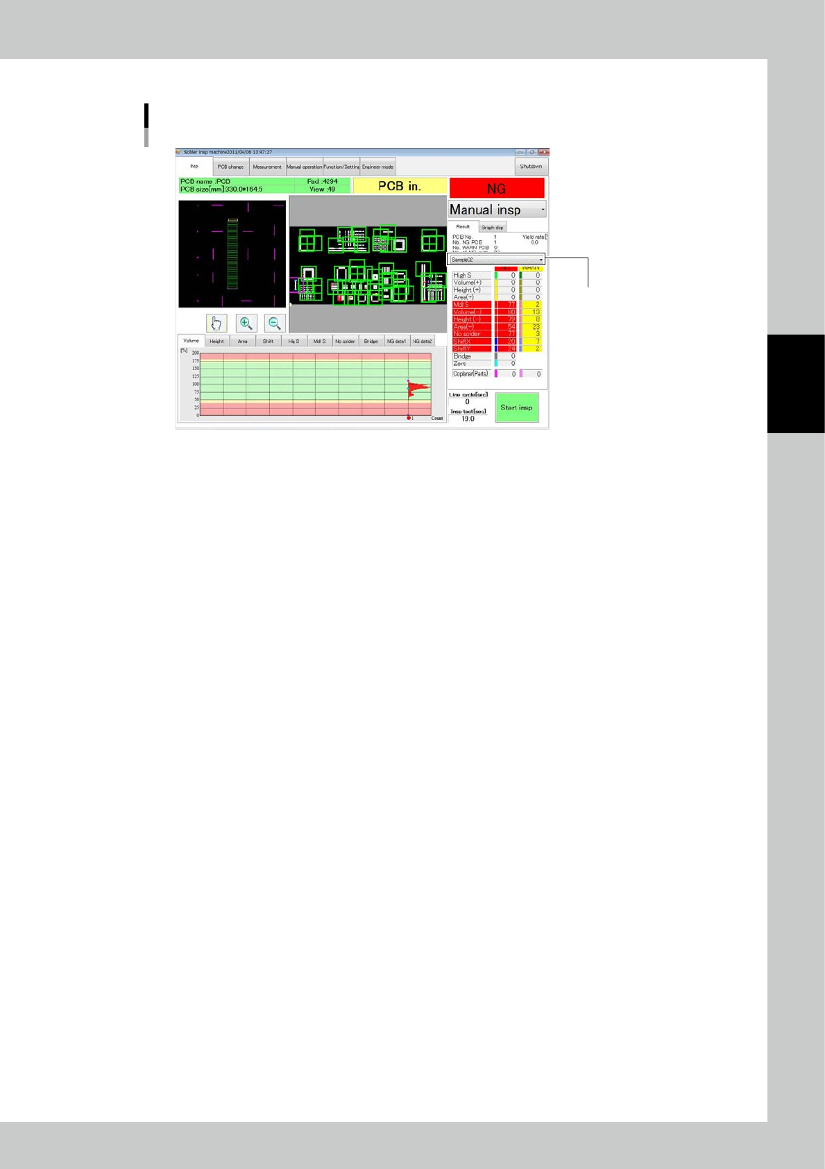
After inspection is finished, the 2D code is displayed in the position shown in the figure.
The 2D code is displayed here.
2D code check
24302-KMN-00
3-4
3
Optional Functions
1.4 Light Amount Adjustment
1. Light amount adjustment
Select Engineer Mode
→
[Edit]
→
[Light Amount Adjustment]
→
"Special insp" tab
→
[2D code] in this order.
The screen shown in Fig. is displayed.
Light amount adjustment screen
24303-KMN-00
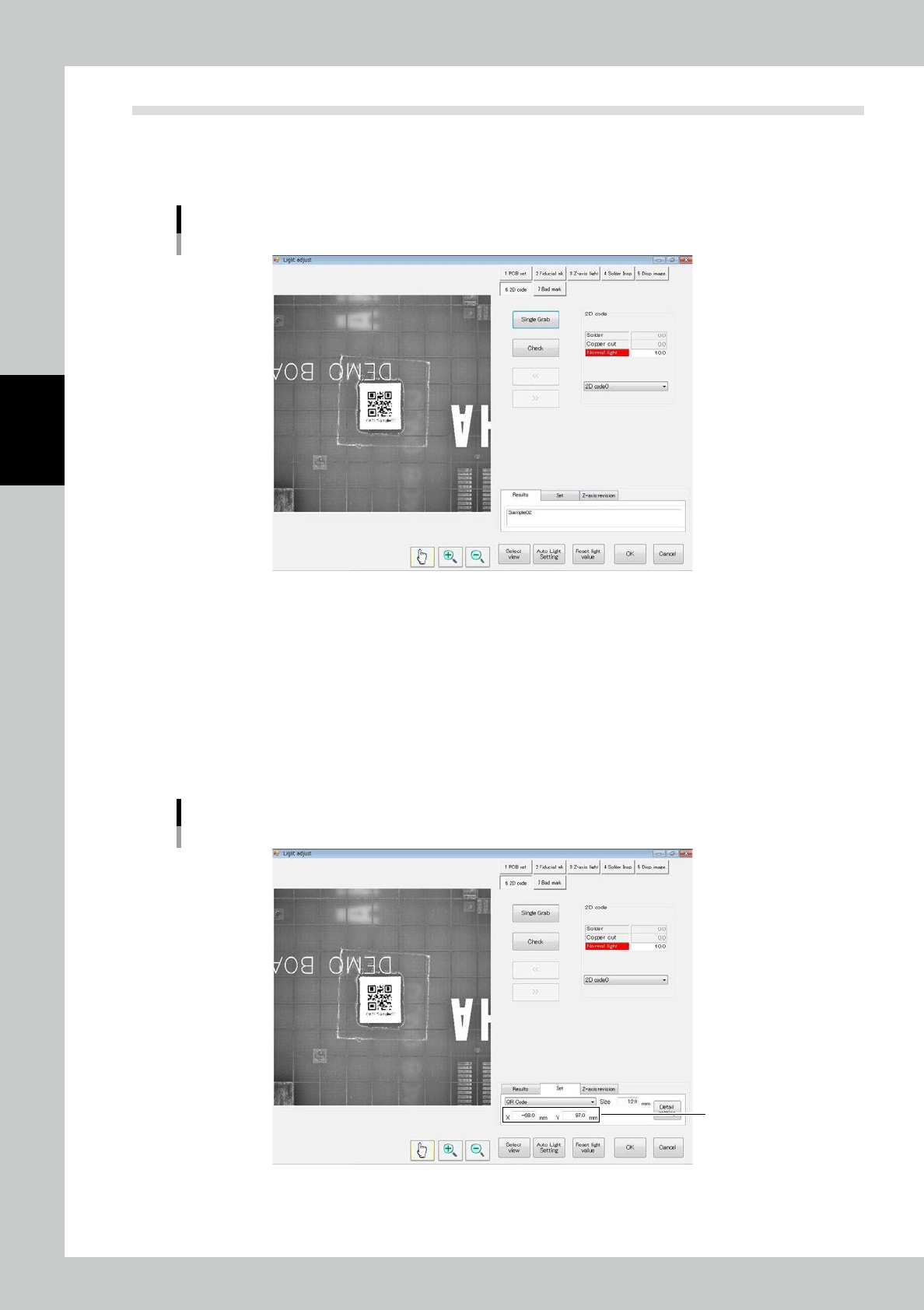
2. Registering coordinates
Adjust so that the 2D code coordinates are in the inspection view field.
If the 2D code is in the inspection view field, there is no need for adjustment.
Enter each of the X and Y coordinates.
※ Coordinates
From zero position of the PCB,
X: Positive toward the right on the screen, negative toward the left
Y: Positive toward the top of the screen, negative toward the bottom.
Coordinate adjustment screen
Coordinates
24304-KMN-00
3-5
3
Optional Functions
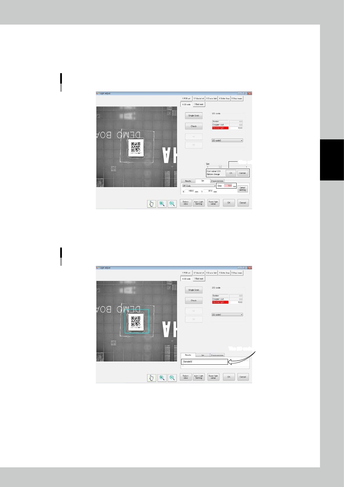
3. Registering the size
The inspection area of the 2D code can be adjusted.
The blue rectangular frame in the center indicates the inspection area.
There is no need to adjust if the 2D code is in the inspection area.
Use the slide bar to adjust the size.
Size adjustment screen
Size adjustment screenSize adjustment screen
24305-KMN-00
4. Registering the light amount
Touch the "Results" tab and adjust the value of the regular light source. Touch [Single Grab] and [Check] and check that
data is displayed in the "Results" field.
The 2D code is displayed here.The 2D code is displayed here.
Adjustment result screen
24306-KMN-00
If the result is good, touch [Save] and [Adjust end] buttons to finish adjustment.
If the result is an error, the "2D code read error" message is displayed.
Check the position, light amount and data code type.